Structure & Reactivity in Chemistry
IC. Ionic Compounds
IC5. Structures of Ionic Solids
The structure of ionic solids is determined by how the cations and anions can pack together. Generally, one of the ions adopts a standard packing structure, like the metal atoms in a metallic solid. The counterions then fit into the holes or interstitial spaces among these ions. It is pretty common for the anions to form a close-packed structure, and for cations to find room in the resulting holes, but sometimes it is the other way around.
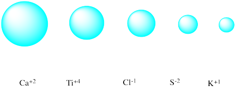
Match each isoelectronic ion with the correct picture of its radius.
Problem IC5.2.
Why might anions more commonly pack into a close-packed structure, rather than the cations?
The holes between the atoms have particular coordination numbers and geometries. There are many possible holes of different shapes where a counterion can find room. However, some of these geometries are very common.
For example, in the center of a simple cube, there is room for an additional atom. This atom is described as sitting in a cubic hole.
Figure IC5.1. An ion in a cubic hole.
The above drawing emphasizes the relationship between the central atom and the atoms that form the corners of the cube. The central atom is in a cubic coordination geometry. Alternatively, we could describe the coordination number of the central atom. Instead of describing the shape formed by the surrounding atoms, we simply count the number of near neighbours. In this case, the coordination number of the central atom is 8. We can think of the central atom as sharing ionic bonding with its eight near neighbours.
An atom in a cubic hole might be viewed more easily if we draw lines between the various atoms at the corners of the cube, however. In that way,we can see more clearly the cubic shape of the cage in which the central atom is sitting.
Figure IC5.2. An alternative view of an ion in a cubic hole.
Another common interstitial space in ionic solids is an octahedral hole. An octahedral hole forms in between two close-packed layers. Because the atoms in the layers are packed more tightly than in a simple cube, this octahedral hole is generally a little smaller than a cubic hole.
Figure IC5.3. An octahedral hole.
An octahedral hole is a space in between six atoms. The six atoms are spread as far apart from each other as possible.
Figure IC5.4. An atom in an octahedral hole.
A third, common type of interstitial space is a tetrahedral hole. Tetrahedral holes, like octahedral holes, are found between two close-packed layers.
Figure IC5.5. A tetrahedral hole.
A tetrahedral hole is a space in between four atoms. The four atoms are spread as far apart from each other as possible.
Figure IC5.6. An atom in a tetrahedral hole.
Problem IC5.3.
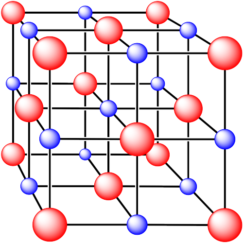
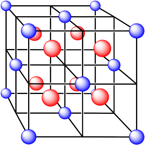
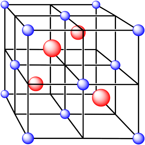
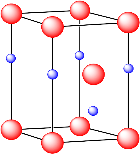
In the following structures, the anions are represented in red and the cations are represented in blue. For each structure,
a) identify the type of unit cell that is visible
b) identify the type of hole occupied by the counter ion
c) identify the fraction of those holes that are occupied
d) identify the number of anions and cations in the unit cell
e) state the empirical formula (the lowest possible ratio of atoms in the material)
i. The ions are formed from cesium and chlorine.
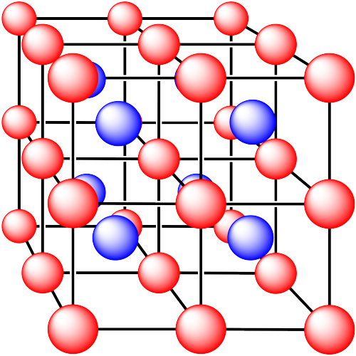
ii. The ions are formed from sodium and chlorine.
iii. The cations are formed from calcium and the anions are formed from fluorine.
iv. The cations are formed from zinc and the anions are formed from sulfur.
v. The cations are formed from zinc and the anions are formed from sulfur.
Additional Information on solid structures:
Visualization of solid state structures: unit cells, etc.
This site was written by Chris P. Schaller, Ph.D., College of Saint Benedict / Saint John's University (retired) with contributions from other authors as noted. It is freely available for educational use.

Structure &
Reactivity in Organic, Biological and Inorganic Chemistry
by Chris Schaller is licensed under a
Creative Commons Attribution-NonCommercial 3.0 Unported License.
Send corrections to cschaller@csbsju.edu
Navigation:
Back to Structure & Reactivity Web Materials