Reactivity in Chemistry
Oxidative Phosphorylation
OP4. Complex III
Complex III accepts electrons from both Complex I and Complex II. The electrons arrive in the form of ubiquinol, UQH2, which delivers two electrons and two protons and is converted back to ubiquinone, UQ. The ubiquinone then shuttles back to Complex I or Complex II to collect more electrons.
Complex III is the destination for electrons arriving from both Complex I and Complex II.
Complex III uses energy released in downhill electron transfers to pump more protons across the inner mitochondrial membrane.
The proton gradient across the membrane is used to drive ATP formation at Complex V.
Complex III then sends its electrons on to Complex IV.
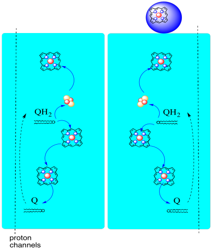
The path of electrons through Complex III is shown below. Note that the complex is a dimeric structure, with two equivalent paths: one shown on the left and the other on the right. Electrons are delivered from UQH2, ubiquinol, in the middle of the picture, traveling upward to the mobile cytochrome c at the top. A second electron pathway allows travel downward in the picture, toward another molecule of ubiquinone, which recycles the electrons in a loop.
Complex III features an unusual, diverging electron pathway.
One electron travels on toward cytochrome c.
The second electron is eventually recycled into another ubiquinol.

Figure OC4.1. A simplified overview of Complex III.
The X-ray structure of Complex III is shown in cartoon form below. The inner mitochondrial membrane would intersect the upper middle portion of the complex. The majority of the complex projects below, into the matrix (the bottom of the picture, in this orientation) although a significant amount also protrudes into the intermembrane space.
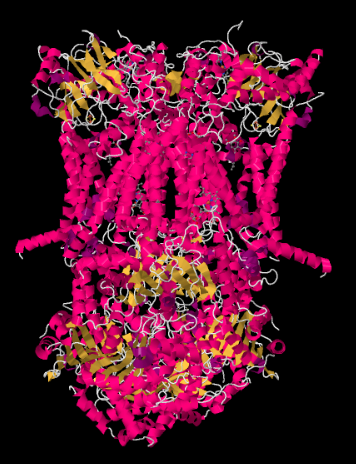
Figure OC4.2. The experimentally observed structure of Complex III (Gao et al).
Complex III continues the electron transport chain, sending electrons to higher reduction potential (and lower free energy) and towards a meeting with molecular oxygen in Complex IV. Protons are also pumped from the mitochondrial matrix, across the inner mitochondrial membrane and into the intermembrane space. At the same time, a second electron route results in an effective recycling of half the electrons that come into the complex, increasing the number of protons pumped per electron arriving at Complex III.
It has been suggested that the electron-recycling loop provides a mechanism for drawing more protons up from the matrix.
We can see this unusual arrangement if we ignore the proteins to reveal the ligands, below. The complex can more clearly be seen as a dimer; the left half of the picture is exactly the same as the right, although reflected the opposite way. Electrons enter the complex via the mobile carrier, ubiquinol, visible on the right and left side of the picture about halfway down; you can see the ringand a chain hanging from it.
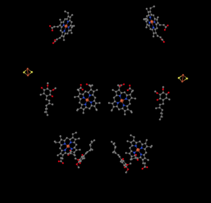
Figure OC4.3. The close-up of key players in electron transport in Complex III (Gao et al).
When UQH2 binds to Complex III, one electron is sent on to an FeS cluster, whereas the second is sent to an iron heme center, called heme BL. The FeS cluster is visible just above the ubiquinol and to the edge of the picture. The heme BL is toward the center of the picture.
Although it isn't apparent in the X-ray picture shown, this FeS cluster is different than the ones that you saw earlier. This one is held in place with different amino acid side chains. You can't see that in the picture because the entire protein has been left out, along with those amino acids that are binding to the cluster. Whereas most FeS clusters are held in place exclusively by cysteines, this cluster is held in place by two cysteiens on one side but by two histidines on the other. This peculiar FeS cluster is called a Rieske cluster.
Rieske clusters are important because they are "high potential FeS clusters". That means that they have exceptionally positive reduction potentials compared to other FeS clusters. The reduction potential of any ligand in a protein is highly dependent on its environment, and so there is a wide range of values in most cases. That's true for iron sulfur clusters; normal ones have reduction potentials that range from -1.0 V to about +0.05 V. Rieske clusters have potentials that range from about 0V to about 0.4 V.
From the FeS cluster, the electron is sent on to another iron heme center in a membrane-bound unit called cytochrome c1. Cytochrome c1 can be seen at the top of the picture. Because this picture is oriented in the same way as the other X-ray structures of the respiratory complex, we can see that this electron is getting transported up toward the intermembrane space. Finally, this electron is transferred to another heme, but this heme is bound in a small, mobile protein, called cytochrome c. Cytochrome c is another mobile electron carrier. It carries the electron on to complex IV. We'll get back to the cytochrome c a little later.
Before we get to that, where does the other electron go? From heme BL, the second electron is passed to another iron porphyrin complex, heme BH. That's toward the bottom of the picture, so this electron is actually getting sent back toward the matrix. Waiting by the heme BL, however, there is another ubiquinone, UQ. It's waiting for the electron. It will actually wait for two, then leave its dock and go back around to the ubiquinol (UQH2) binding site to deliver the electrons again.
Why bother? Why not just send the electrons on their way properly the first time around? It seems they are getting recycled for some reason. It's believed that this diversion allows for additional protons to be pumped across the mitochondrial membrane. When the second ubiquinone gets reduced to ubiquinol via the acceptance of two electrons, it also picks up two more protons from the matrix below. Those protons will eventually get passed along toward the intermembrane space when the ubiquinol gets oxidized again. This recycling, and squeezing out a couple of extra protons to increase the proton gradient, is called the Q loop.
The advantage of the Q-loop is explained in the following diagram. In the diagram, inputs to complex III are shown in red, outputs are shown in blue, and recycled elements are in green. If one ubiquinol simply delivered its electrons and protons and was done, there would be two protons delivered per ubiquinol. That's one proton output per electron that was input.
A second ubiquinol would do exactly the same thing. There would be four protons output for four electrons initially input. That's still one proton output per electron that was input.
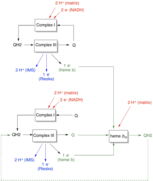
Figure OC4.4. A schematic of the Q-loop.
If, instead, one electron is recycled each time, then every second ubiquinol leads to the delivery of an extra pair of protons. That's because in picking up the recycled electrons, a ubiquinone has had to travel back to the matrix side of the membrane and pick up two more protons. Overall, that means six protons are delivered for four electrons input, or 1.5 protons output per electron input. Since the proton gradient is what is generating the ATP, then by increasing the number of protons pumped per electron coming in, efficiency is increased.
The Q-loop increases the number of protons pumped per electron input into the system.
Now let's get back to the outgoing electron carrier, cytochrome c, which will ferry the electrons on to Complex IV. In the picture below, from a different X-ray crystal structure, the Complex has been found with a cyctochrome c docking at the binding site. Cytochrome c is a pink globular protein attached at the top of the picture, on the left half of the dimer as we look at it here. It's sitting at the edge of the intermembrane space, which is aqueous media. Unlike the ubiquinone, which slips along through the lipid bilayer of the membrane, cytochrome c rolls or slides or swims over the top to its destination.
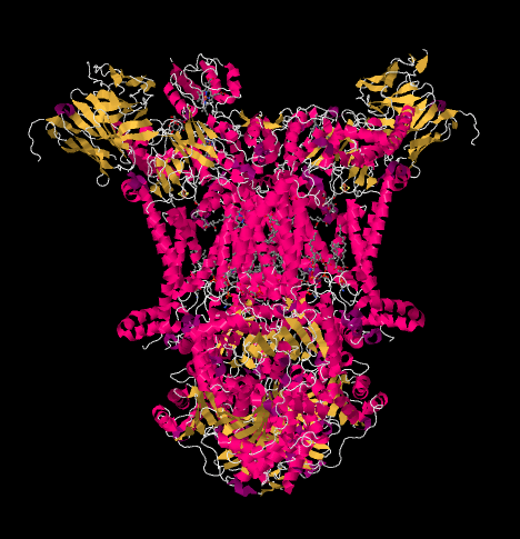
Figure OC4.5. A different view of Complex III, with a bound cytochrome c (Solmaz et al).
The same view is shown below without the protein. The bottom part of the picture is pretty cluttered with lipids, and there is a sugar hanging around to the upper left, but right at the very top you can see the iron porphyrin that is nestled inside the cytochrome c.
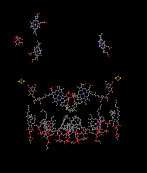
Figure OC4.6. Another close-up of Complex III, with a bound cytochrome c (Solmaz et al).
A closer look at an X-ray structure of a cyctochrome c, below, shows a relatively simple picture compared to the complexes we have been looking at. There are a couple of helices, a couple of sheets, some loops, and that iron porphyrin or heme again. A few sulfate ions are floating around nearby, as well as a couple of glycerol molecules, probably introduced during purification or crystallisation of the protein. Note that the heme is found at the edge of the protein. That location may make it easier for electron transfer from Complex III, or to Complex IV.
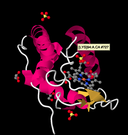
Figure OC4.7. The experimentally observed structure of cytochrome c (Enguita et al).
Cytochrome c is the final destination of electrons moving through Complex III.
Cytochrome c is a mobile, one-electron carrier.
Cytochrome c is actually a small, hydrophilic protein.
Cytochrome c is found above the mitochondrial membrane, at the edge of the intermembrane space.
What keeps cyctochrome c from wandering off into the intermembrane space? If it did so, it would interrupt the efficient flow of electrons. It is possible that cytochrome c moves back and forth between Complex III and Complex IV via a mechanism called "steering". In steering, the carrier is guided along a pathway via complementary charges. For example, if the membrane is negatively charged because of polar groups on the membrane surface, then positive charges on the surface of the cytochrome c may restrict its movement to the membrane surface. That alone would reduce its mobility from three dimensions (anywhere in the intermembrane space) to two dimensions (anywhere on the membrane surface). It is possible that additional interactions reduce its mobility even further to a one-dimensional track between the two complexes.
Steering, based on complementary charges, keeps the cytochrome c from being lost in the intermembrane space.
Problem OP4.1.
Suggest possible amino acid residues at the surface of cytochrome c that may help it stay on a negatively charged membrane surface.
Problem OP4.2.
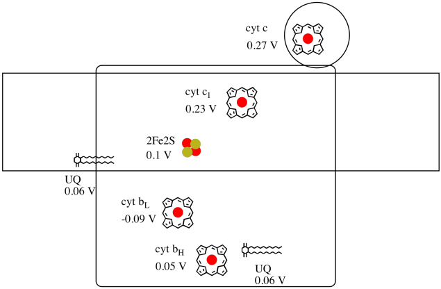
It's difficult to measure the reduction potential of an individual site within a protein. However, researchers have been able to estimate these values by measuring EPR spectra under various conditions. Assuming the reduction potentials below, draw a reaction progress diagram for transport of an electron all the way from the initial ubiquinone donor all the way to cytochrome c.
Problem OP4.3.
Using the values in the figure above, calculate the energy change when an electron is transferred from the 2Fe2S cluster to the cytochrome c1.
Problem OP4.4.
One of the perplexing things about this complex is that, in the electron recycling loop, electron transfer appears to go from an initial ubiquinone to a final ubiquinone, with no overall driving force. However, reduction potentials are very sensitive to environment. Show how nearby arginine residues might make the reduction potential of a ubiquinone more positive.
See the focus page on the structure of Complex III at Biochemistry Online.
X-ray crystal structure of Complex III from: Gao, X., Wen, X., Esser, L., Quinn, B., Yu, L., Yu, C.-A., Xia, D. Structural basis for the quinone reduction in the bc1 complex: a comparative analysis of crystal structures of mitochondrial cytochrome bc1 with bound substrate and inhibitors at the Qi site. Biochemistry 2003, 4, 9067-9080. (1NTZ)
X-ray crystal structure of Complex III with bound cytochrome c from: Solmaz, S.R., Hunte, C. Structure of complex III with bound cytochrome c in reduced state and definition of a minimal core interface for electrontransfer. J. Biol. Chem. 2008, 283, 17542-17549. (3CXH)
X-ray crystal structure of cytochrome c from: Enguita, F.J., Pohl, E., Turner, D.L., Santos, H., Carrondo, M.A. Structural evidence for a proton transfer pathway coupled with haem reduction of cytochrome c" from Methylophilus methylotrophus. J. Biol. Inorg. Chem. 2006 11, 189. (1OAE)
This site is written and maintained by Chris P. Schaller, Ph.D., College of Saint Benedict / Saint John's University (retired) with contributions from other authors as noted. It is freely available for educational use.

Structure & Reactivity in Organic, Biological and Inorganic Chemistry by Chris Schaller is licensed under a Creative Commons Attribution-NonCommercial 3.0 Unported License.
This material is based upon work supported by the National Science Foundation under Grant No. 1043566.
Any opinions, findings, and conclusions or recommendations expressed in this material are those of the author(s) and do not necessarily reflect the views of the National Science Foundation.
Navigation: