Reactivity in Chemistry
Photosynthesis
PS5. Adding a Proton Pump: Cytochrome b6f Complex
The goal of photosynthesis is to produce ATP, which is in turn used to produce carbohydrates through carbon capture. ATP is generated via a proton gradient, which in turn is maintained through an electron transport chain. The cytochrome b6f complex is closely analogous to complex III in oxidative phosphorylation. It plays a major role in generating a protein gradient during photosynthesis.
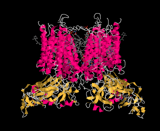
An X-ray crystal structure of cytochrome b6f is shown below. Once again, it is a membrane-bound protein. The stroma lies at the top of the picture and the lumen at the bottom.
Figure PS5.1. X-Ray crystallographic structure of cytochrome b6f from the cyanobacteria, Mastigocladus laminosus.1
The ligand-only view of the structure is provided below. We can see a dimeric structure here, with the left half mirroring the right half. Near the bottom of each dimer, there is a heme. Just above that, we can see an FeS cluster; it is actually a 2Fe2S cluster, and specifically a Rieske cluster. That is just like the FeS cluster in complex III. Rieske clusters have very positive reduction potentials because of their unique coordination environment.
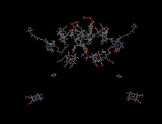
Figure PS5.2. Ligand-only view of the X-Ray crystallographic structure of cytochrome b6f from the cyanobacteria, Mastigocladus laminosus.1
Above the Rieske clusters, things get a little more cluttered. There are a couple of more hemes on each side with their red iron atoms, as well as a chlorophyll with its magnesium shown in yellow. In addition, there are lots of terpenoid structures, such as carotenoids. Not all of these ligands have roles that are clearly understood, and we will focus on the bare essentials.
Cytochrome b6f is shown in a simplified form in a diagram below. Onle one of the two units in the dimer is shown. Each unit is itself a relatively small complex, containing only four proteins: cyctchrome b6, cytochrome f, a Rieske protein, and "subunit IV", whose role is not well understood.
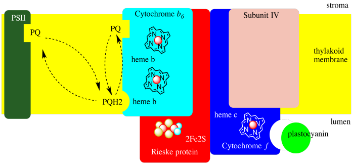
Figure PS5.3. Simplified picture of some main features of cytochrome b6f. The picture shows a monomer only.
Photosystem II eventually produces a mobile plastoquinol which travels through the thylakoid membrane to cytochrome b6f, binding near the lumen side of the membrane. The plastoquinone releases its two electrons and its two protons and can return to photosystem II for more. Alternatively, the plastoquinone might just travel across to the stroma side of the mebrane, where it can pick up two new protons from the stroma as well as two more electrons.
Where do the two electrons come from? They are recycled in the "Q-loop". When it arrives at cyctochrome b6f, instead of sending both electrons along the electron transport chain, the plastoquinone only sends one electron in that direction. That first electron travels to the Rieske FeS cluster, then to a cytochrome f (that's a cytochrome b found in plants), and finally to a soluble, mobile electron carrier, plastocyanin.
The other electron travels in the other direction, back toward the stroma, via a pair of hemes. After two plastoquinols have delivered their electrons to cytochrome b6f, a waiting plastoquinone can be reduced again to plastoquinol, picking up two more protons from the stroma. That plastoquinol can then travel back across the membrane to deliver its two protons to the lumen. One of its electrons gets sent down the electron transport chain, and the other electron gets recycled (again).
The advantage of the Q-loop is explained in the following diagram. In the diagram, inputs to cytochrome b6f are shown in red, outputs are shown in blue, and recycled elements are in green. If one plastoquinol simply delivered its electrons and protons and was done, there would be two protons delivered per plastoquinol. That's one proton output per electron that was input.
A second plastoquinol would do exactly the same thing. There would be four protons output for four electrons initially input. That's still one proton output per electron that was input.
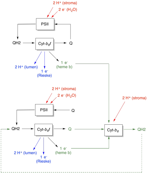
Figure PS5.4. Diagram showing protons pumped per electron consumed, with the addition of the Q-loop. Inputs are shown in red and outputs in blue. Recycled elements are provided in green.
If, instead, one electron is recycled each time, then every second plastoquinol leads to the delivery of an extra pair of protons. That's because in picking up the recycled electrons, a plastoquinone has had to travel back to the stroma side of the membrane and pick up two more protons. Overall, that means six protons are delivered for four electron input, or 1.5 protons output per electron input. Since the proton gradient is what is generating the ATP, then by increasing the number of protons pumped per electron coming in, efficiency is increased.
Problem PS5.1.
The efficiency advantage is even greater than that described above. The Q-loop is thought to double the amount of protons pumped by cytochrome b6f. Explain why.
The electron transport chain through cytochrome b6f is rather short. The electron is first passed to a "high-potential FeS cluster", or Rieske cluster. It differs from most FeS clusters in that two of the amino acid residues that bind it in the protein are histidines, rather than the usual cysteines. Rieske clusters usually have higher reduction potentials than other FeS clusters. They were one of the last in a series of FeS clusters encountered in the electron transport chain in oxidative phosphorylation, and their more positive reduction potential was needed to keep the electron transport chain moving in the right direction.

Figure PS5.5. Coordination environment of the iron atoms in a Rieske FeS cluster.
Problem PS5.2.
The reduction potential of a Rieske FeS cluster is generally more positive than that of a regular FeS cluster, in which the Fe2S2 core is held in place by four cysteines. Explain why.
The final stop for the electron is a small, soluble protein, plastocyanin. The electron carrier in plastocyanin is not an iron, but rather a copper atom. The copper ion, which can toggle between Cu+ and Cu2+, is held in place by two histidines, a methionine, and a cysteine. The plastocyanin transports the electron through the lumen to the next complex, photosystem I.

Figure PS5.6. Coordination environment of the copper ion in plastocyanin.
Problem PS5.3.
Use periodic trends to suggest a reason why a copper atom appears later in the electron transport chain, whereas several iron atoms appeared earlier in the chain.
Problem PS5.4.
a) What would be the overall charge on the coordination complex in plastocyanin, assuming the Cu(II) state?
b) What would be the overall charge on the coordination complex in plastocyanin, assuming the Cu(I) state?
c) Based on charge considerations alone, how would you expect the reduction potential of plastocyanin to compare to the Rieske FeS cluster?
1. X-ray crystal structures: Kurisu, G.; Zhang, H.; Smith, J.L.;
Cramer, W.A. Structure of the cytochrome b6f complex of oxygenic
photosynthesis: tuning the cavity. Science 2003,
302,
1009-1014. Images obtained via RCSB Protein Data Bank (1VF5).
This site is written and maintained by Chris P. Schaller, Ph.D., College of Saint Benedict / Saint John's University (retired) with contributions from other authors as noted. It is freely available for educational use.

Structure & Reactivity in Organic, Biological and Inorganic Chemistry by Chris Schaller is licensed under a Creative Commons Attribution-NonCommercial 3.0 Unported License.
This material is based upon work supported by the National Science Foundation under Grant No. 1043566.
Any opinions, findings, and conclusions or recommendations expressed in this material are those of the author(s) and do not necessarily reflect the views of the National Science Foundation.
Navigation: