|

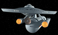
Ptolemy Class Transport
Scratch/Bash
Franz Joseph
Designs
Star Trek Technical Manual
|
 |
Stated scale: |
1/1000 |
 
|
Actual scale: |
unverified |

|
Overall length: |
|
Material(s): |
styrene / resin |
Number of parts: |
|
Stand included? |
|
Decals included? |
|
My Source: |
|
Cost (w/o s&h): |
|

Working on the PNT
Dreadnought conversion kit got me all bugged up to make the rest of the
Franz Joseph cut'n'paste starships from the old ST Tech Manual (SFTM). The Destroyer,
Scout, and Transport are simple enough to scratch'n'bash using Polar Lights TOS
1/1000 Enterprise kits. I began by parting out the pieces from three of Polar's E kits.
The details for the Transport build are below but there are a number of things common to
both builds, and to the Dreadnought and the four
Enterprises.
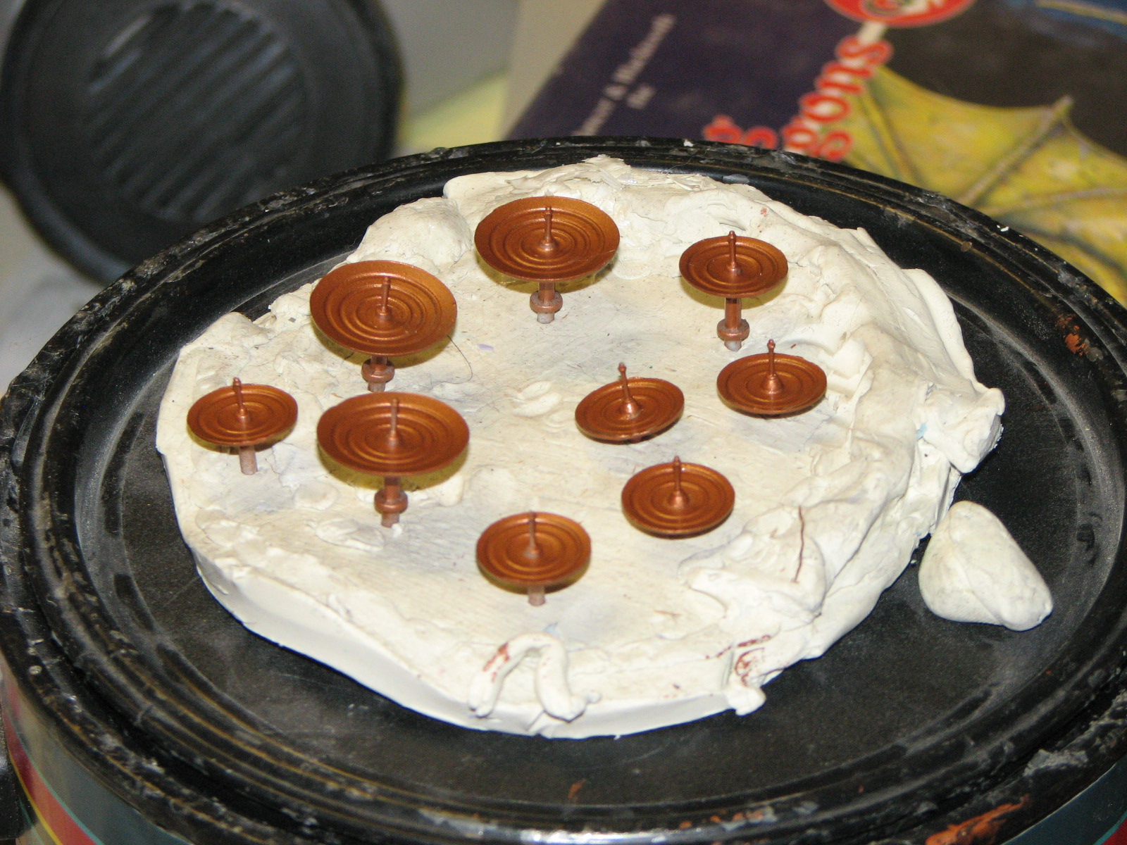
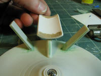
such as deflector dishes and deflector armatures...
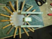
No, it's not a small pizza... 9 dishes painted 1:1 Testors copper and Model
Master leather enamel. 3 of the small dishes are for the destroyer, scout, and
transport, 4 for the Enterprises (3 large, 1 small), two small for the
Dreadnought. And one dish to rule them all, one dish to find them, one di...
oops, nevermind.
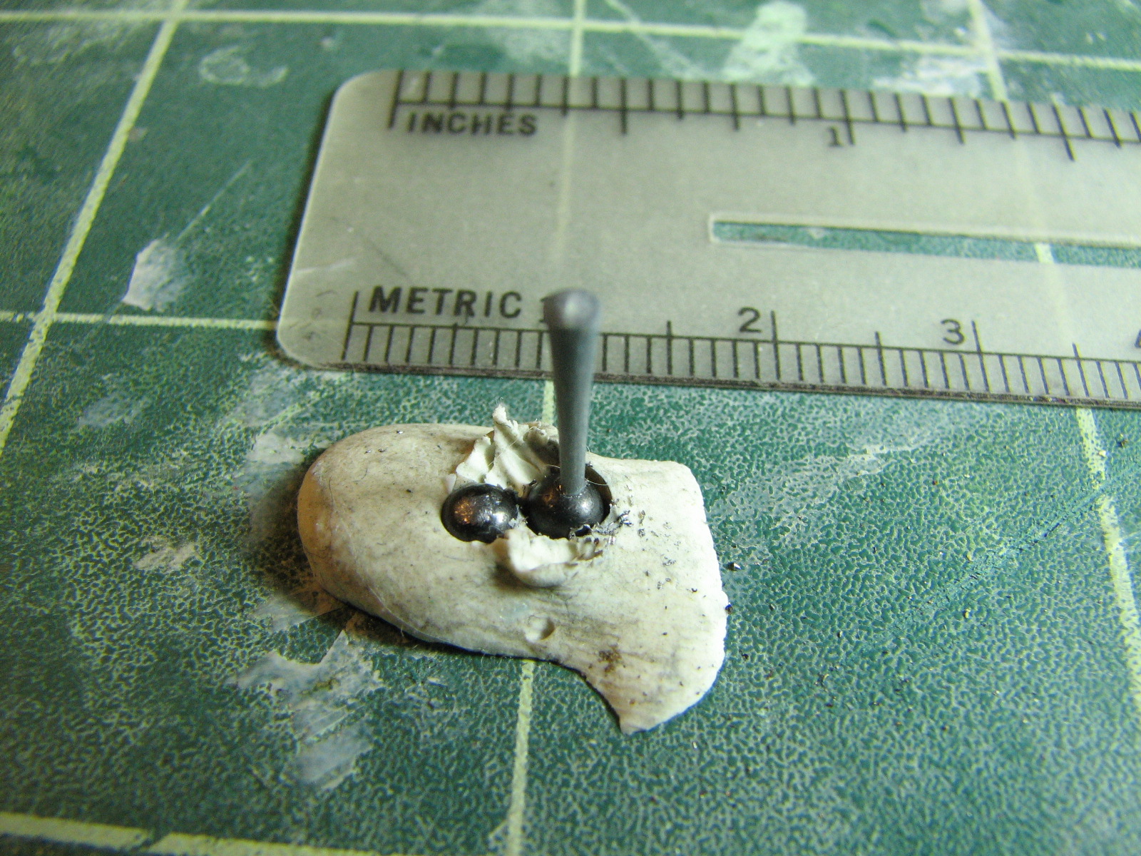
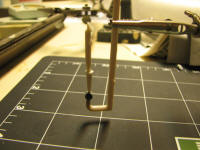
The armature mount is a bit of heat-stretched styrene
sprue and 0.1" lead shot. I set the shot in clay and drilled a small divot into
it, then superglued the styrene to it. This will be the master for an RTV mold
to make castings.

And on the matter of names and numbers, my transport
will be U.S.S. Vanguard, NCC-816, named
after Ocean Vanguard, an early incarnation of the WW-II Liberty class cargo ship.
The starliner module, which I think of more as a colonizer transport, will
probably be named "Belt of Orion." I'll be making a general cargo
module too, but that doesn't need a name.
 |
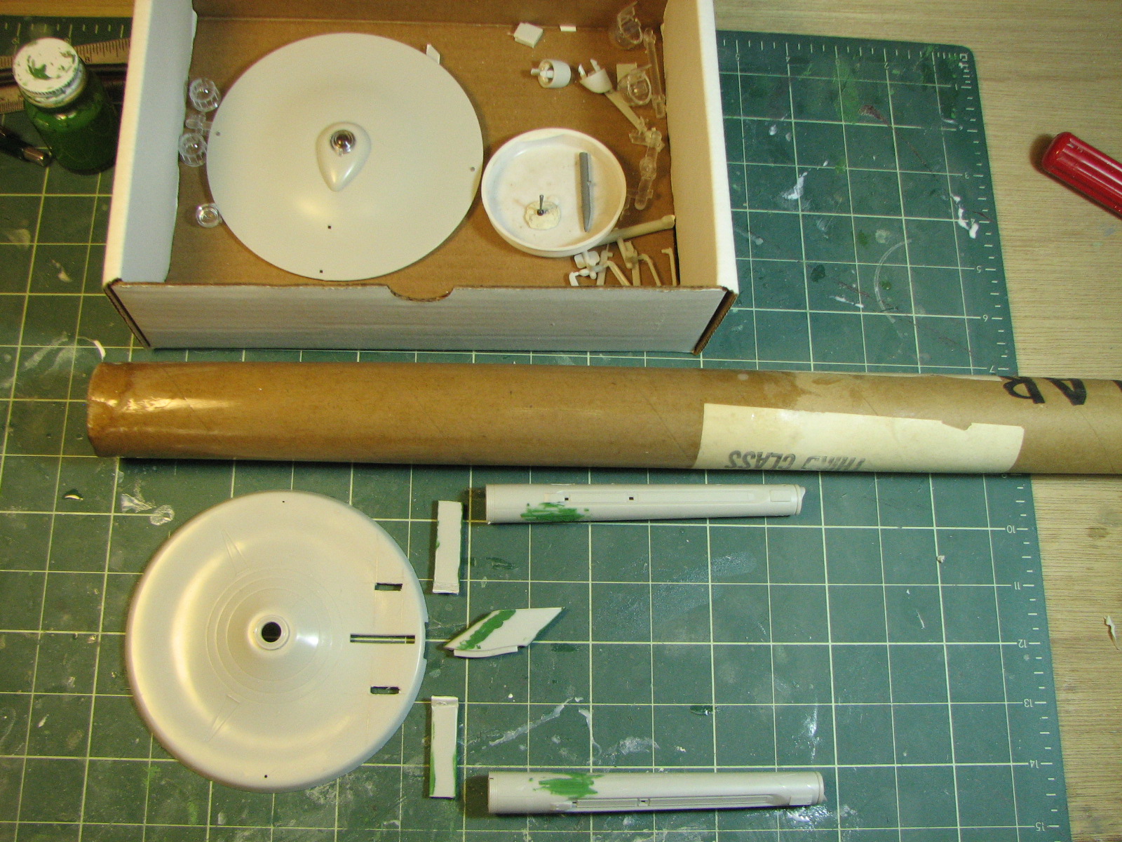
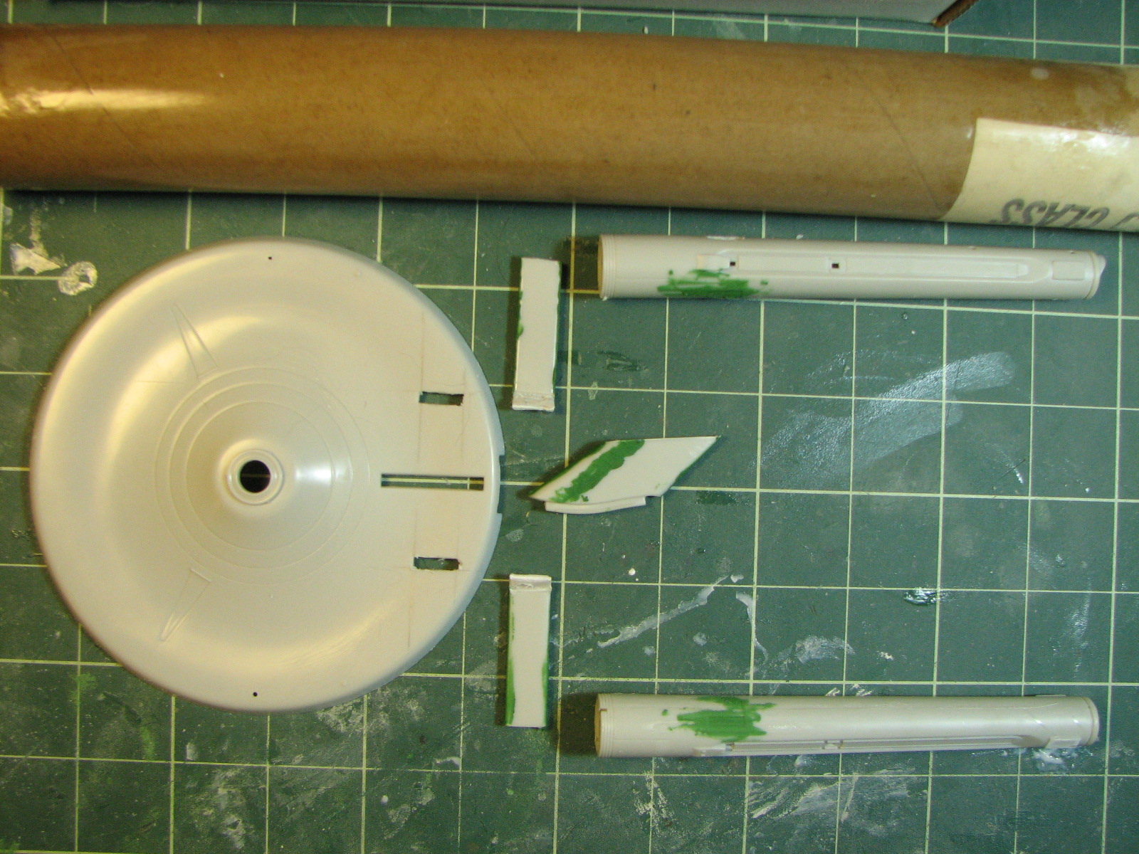
Parts from the Polar Lights kit are:
- Parts for 1 production
saucer
- Dorsal neck cut away from the 2' hull
- Small deflector dish & spike
- Nacelle struts
- Parts for 2 production warp nacelles.
Parts to be scratchbuilt are the deflector dish armature, connector pad, and transport
containers. In this scale, containers are 4cm x 20cm - about 1 9/16" x 7 7/8".
|
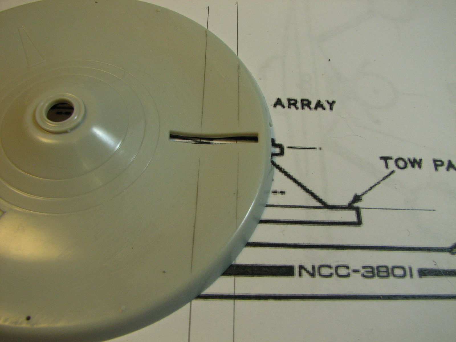
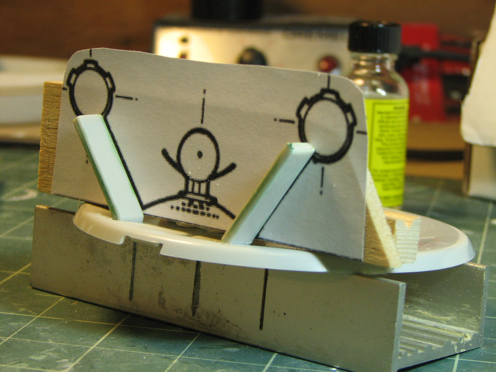
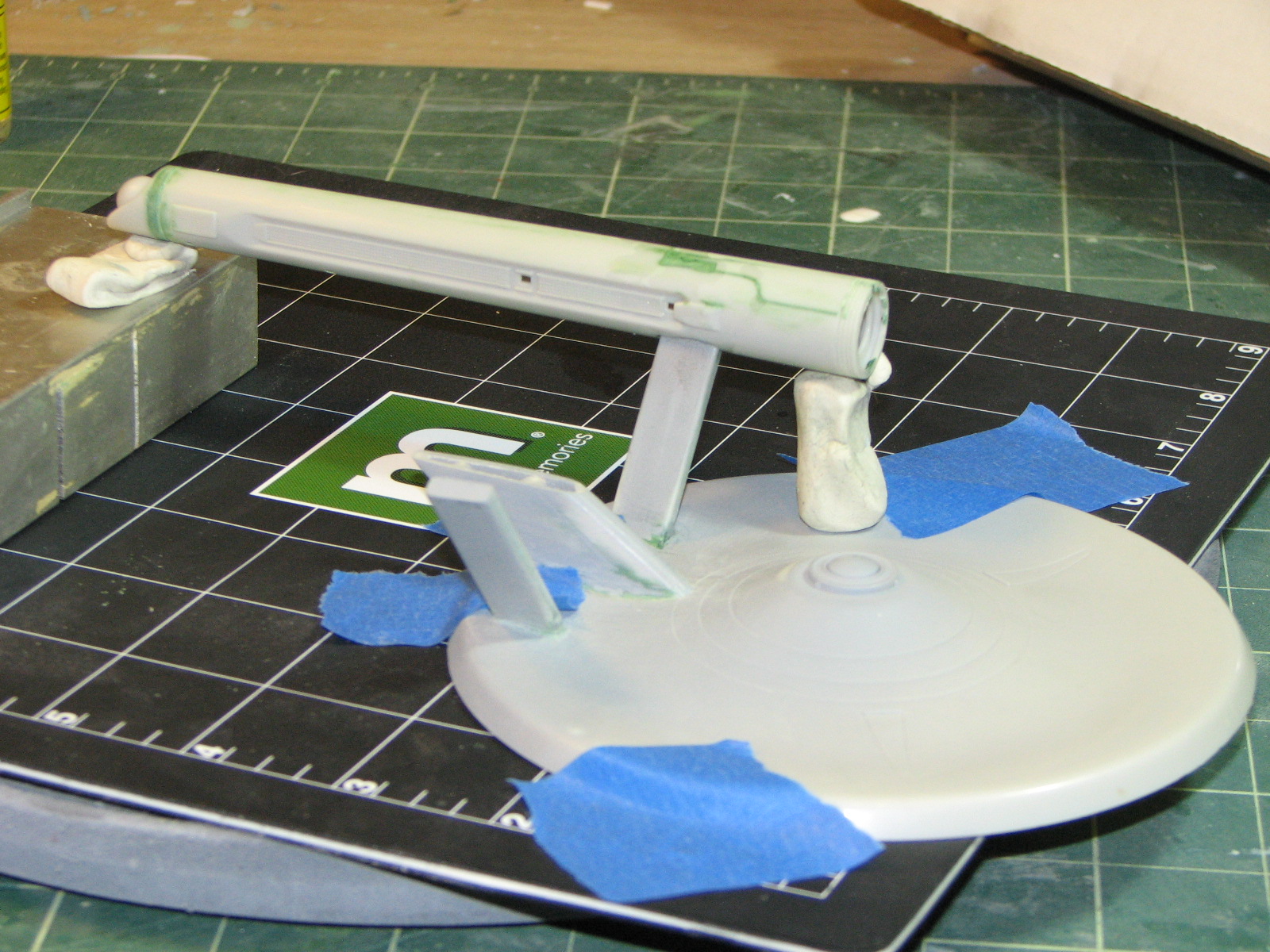
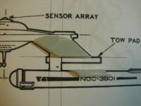
1/25/2011 - I began by marking the location of the nacelle
struts' attachment point on the bottom saucer. I used enlarged-to-scale copies
of the SFTM side and fore drawings of the Transport, aligned the saucer bottom
on them and drew lines for the strut attachment onto the saucer. I then cut the
openings with a Dremel fitted with a cut-off wheel.

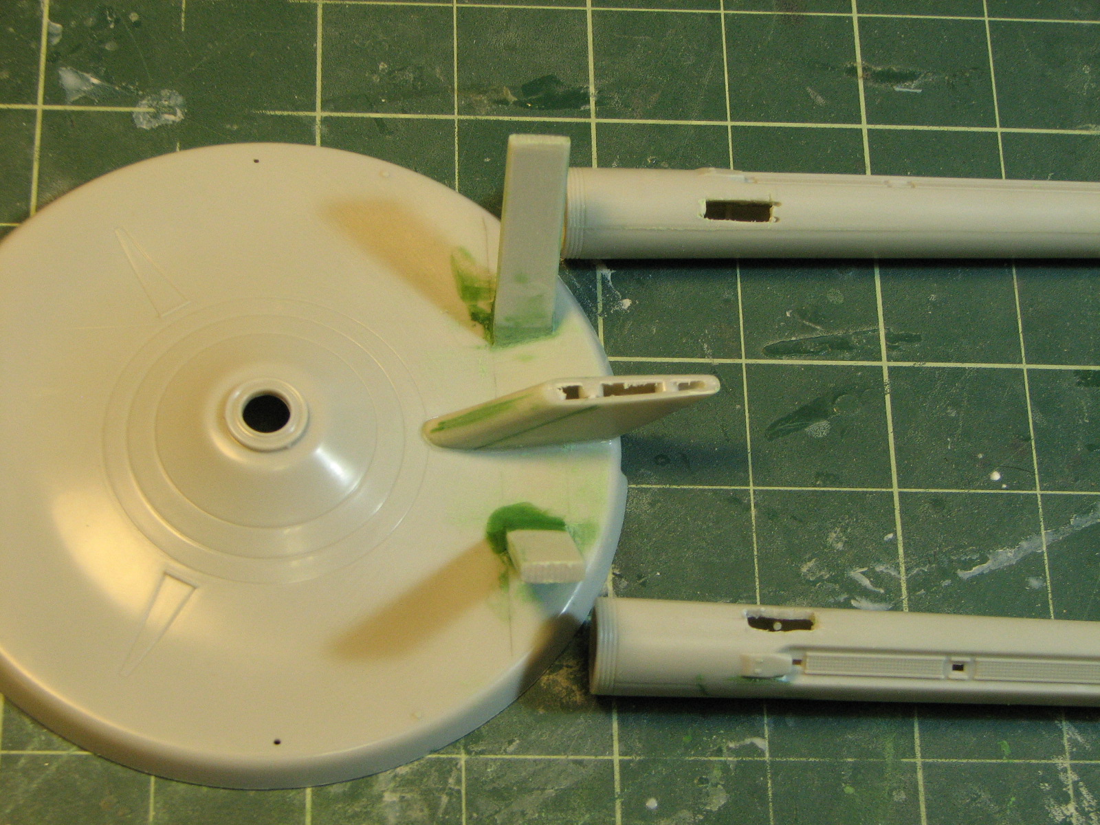
Next I assembled the dorsal neck and trimmed it to length,
then filled the existing nacelle strut attachment holes on the warp nacelles and
assembled the nacelle halves. Again, I used the enlarged drawing to mark the
strut attachment point on each nacelle.
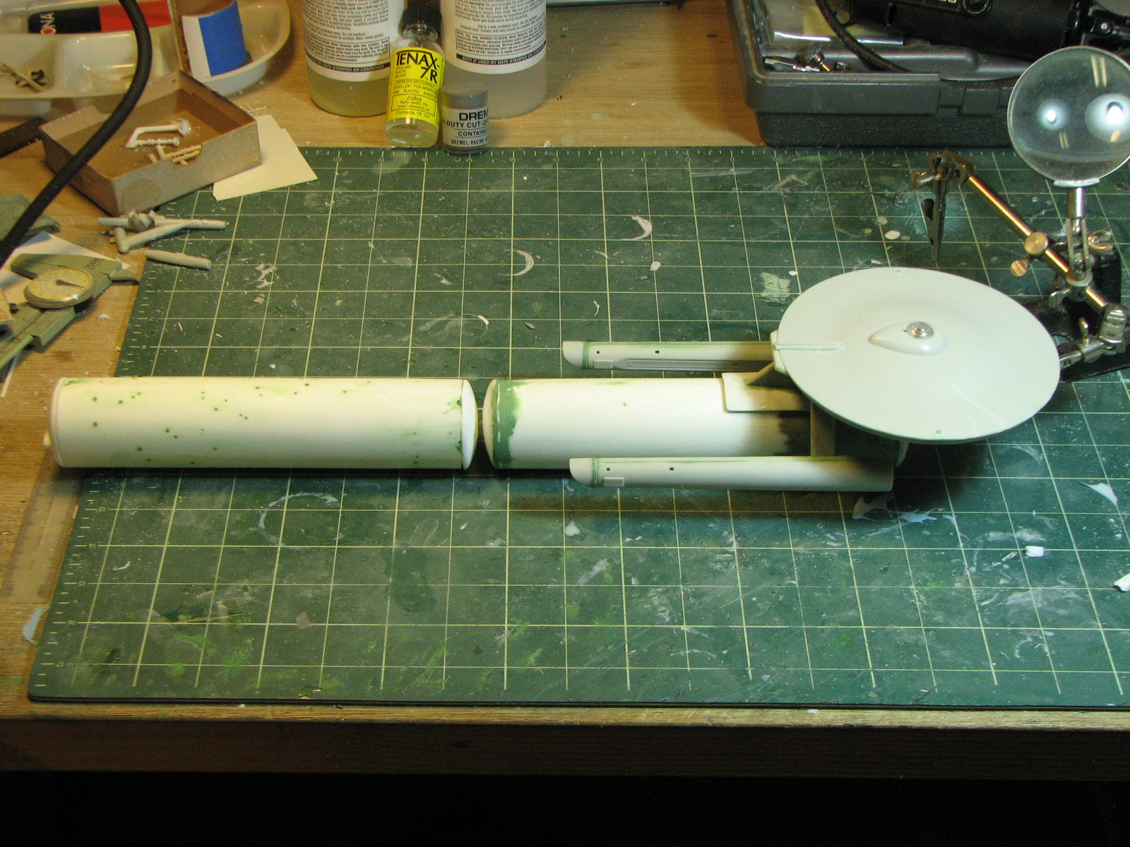
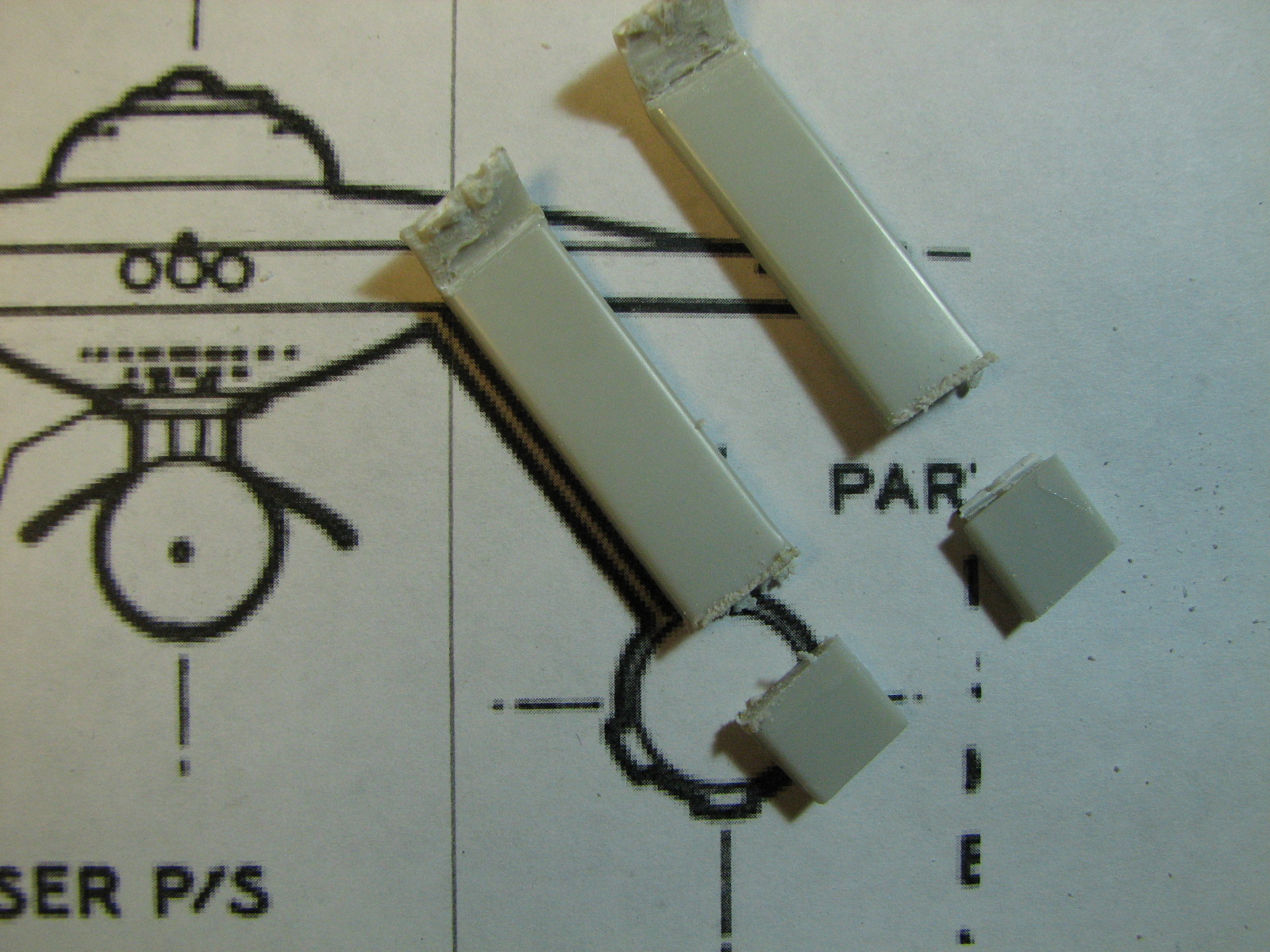
I assembled the nacelle struts, removing the center
section of 2' hull top between the nacelles and cutting the assembly in two.
each nacelle strut needed about 1/2" trimmed away to be the correct length.
I began puttying up seams and excessively-engraved lines.


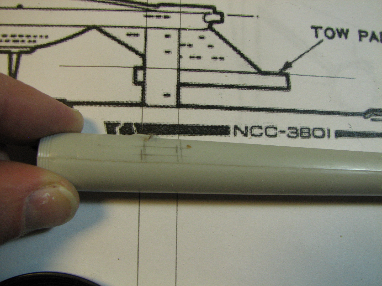
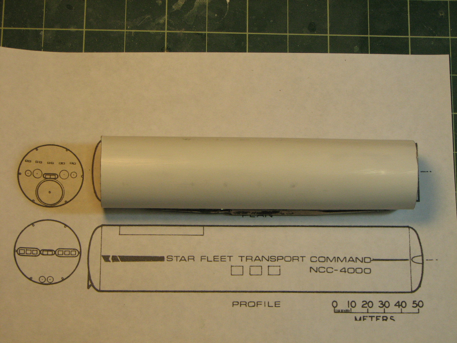
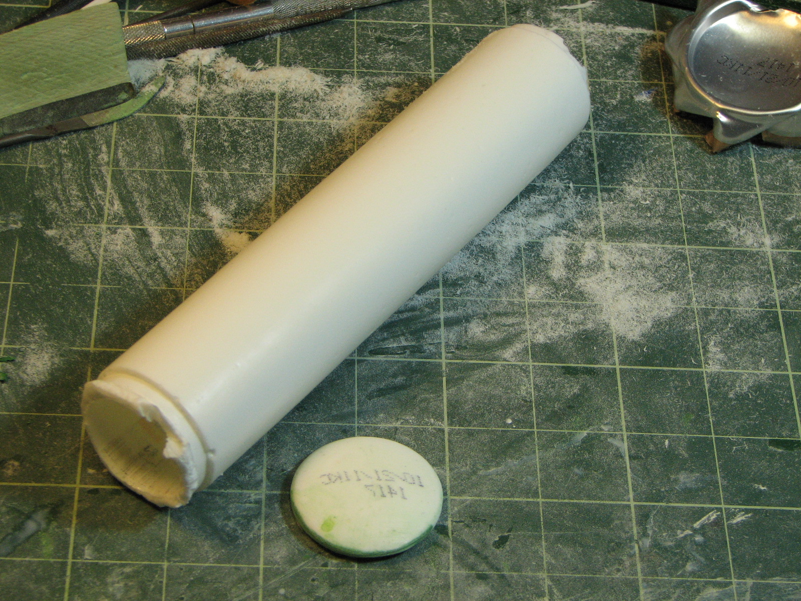
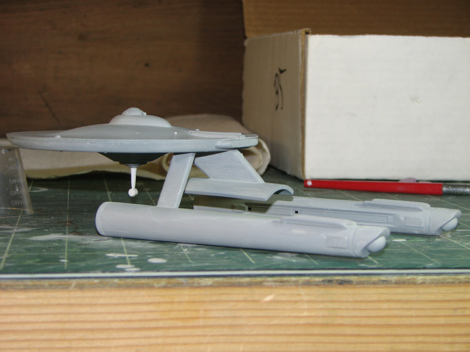
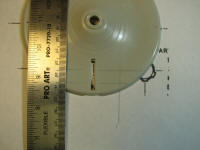
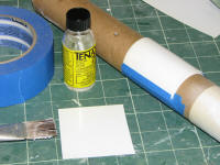
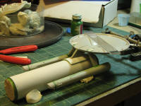
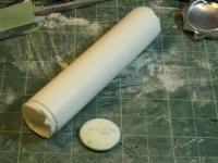
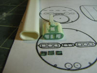
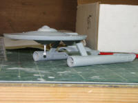
The transport also needs its transport containers. That cardboard mailing tube
next to the parts is 4cm
diameter - the exact size for the 40m diameter transport containers. I'd
been painting / sanding it for about a week with Minwax polyurethane to seal and smooth
the surface so I can pull a mold off it. An ~18cm length of this tube and
scratchbuilds for various endcaps will be the masters for the 200m long
(20cm in scale)
transport cylinders.
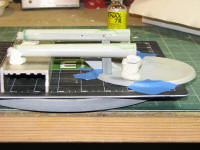
1/27/2011 - Let's see... used a front view printout
mounted on balsa wood to align the nacelle struts for gluing, puttied those up,
attached the dorsal, trimmed out the holes on the nacelles


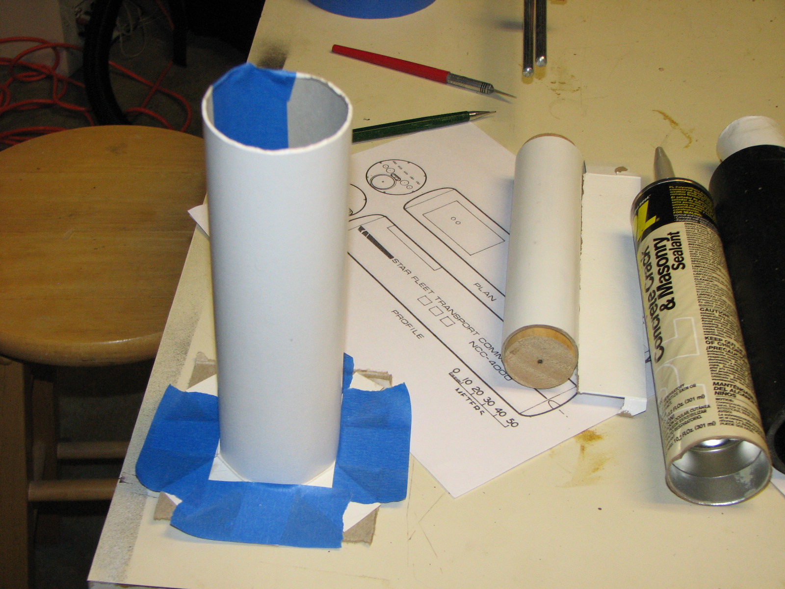
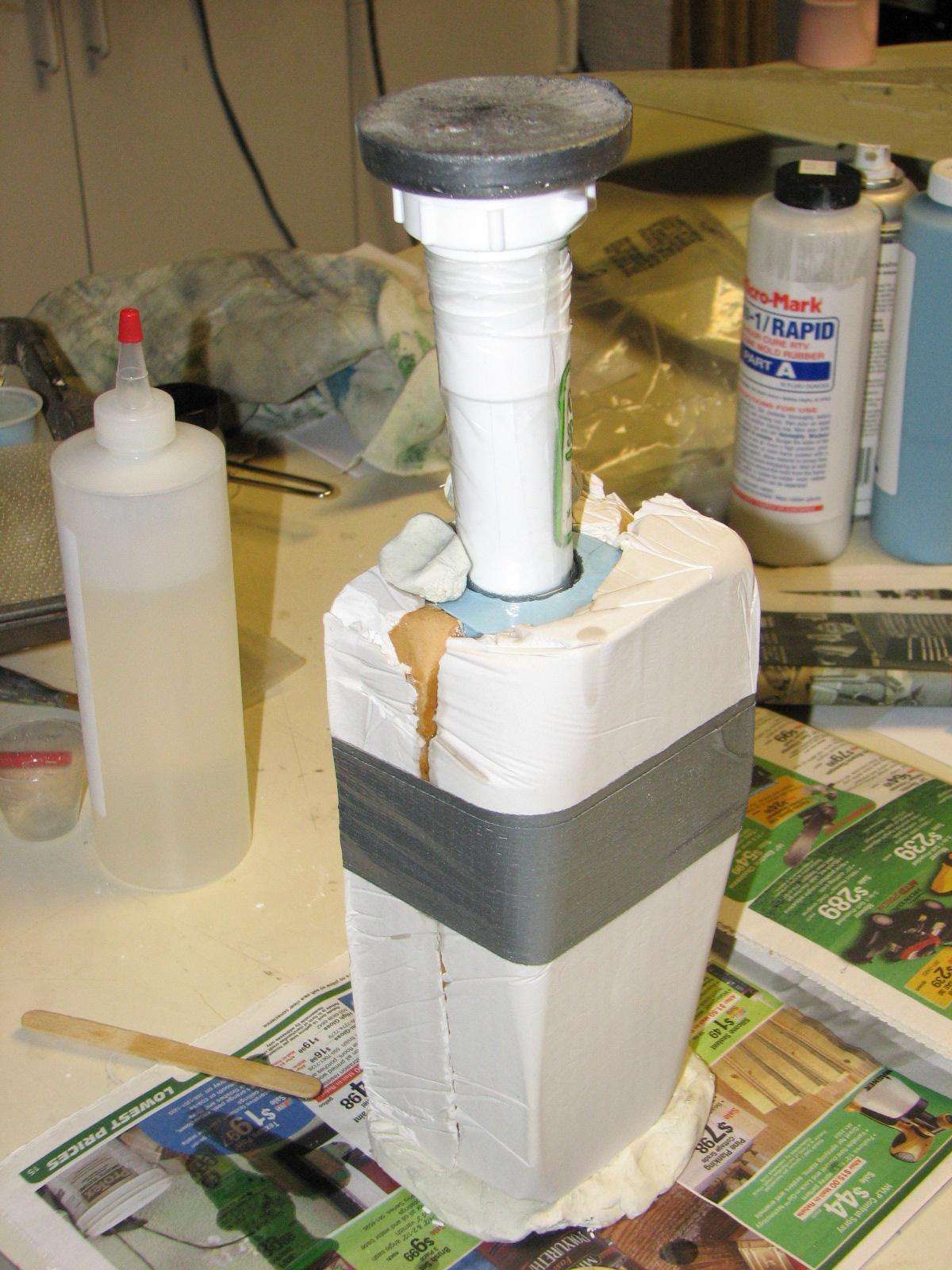
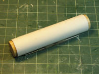
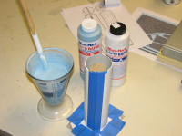
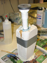
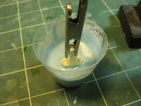
The master for the transport cylinder took on a few more
coats of urethane, then a few coats of white rattlecan paint. When the finish
was smooth, I cut the cardboard tube to length in a miter box w/ handsaw. I
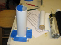
plugged the ends of the tube with 1 1/2" wooden dowel and began prepping a
container for pouring RTV around the master to make a mold of it. The container
is fiberboard formed and taped around a 2 1/2" PVC pipe, glued to a base so it
stands upright. After the RTV pour I moved on to...

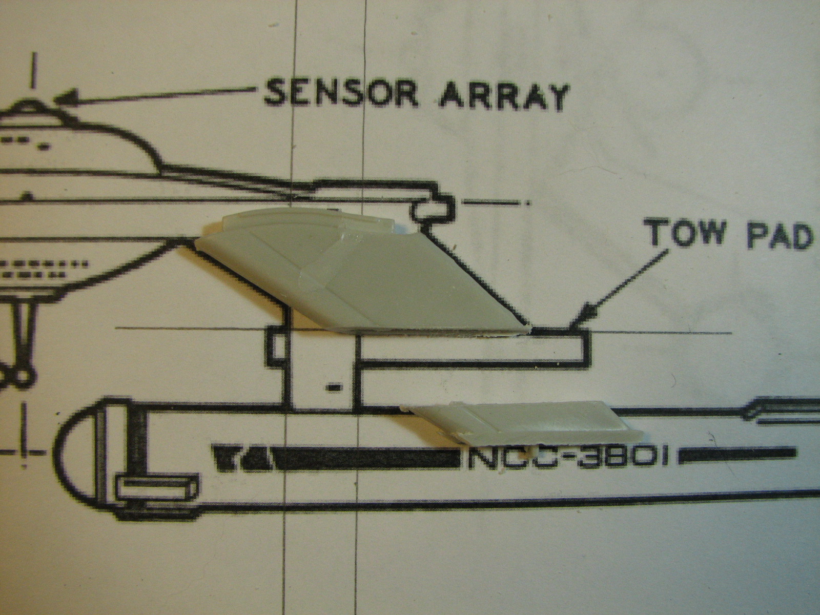
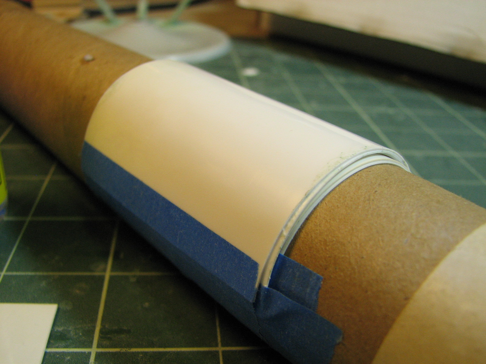
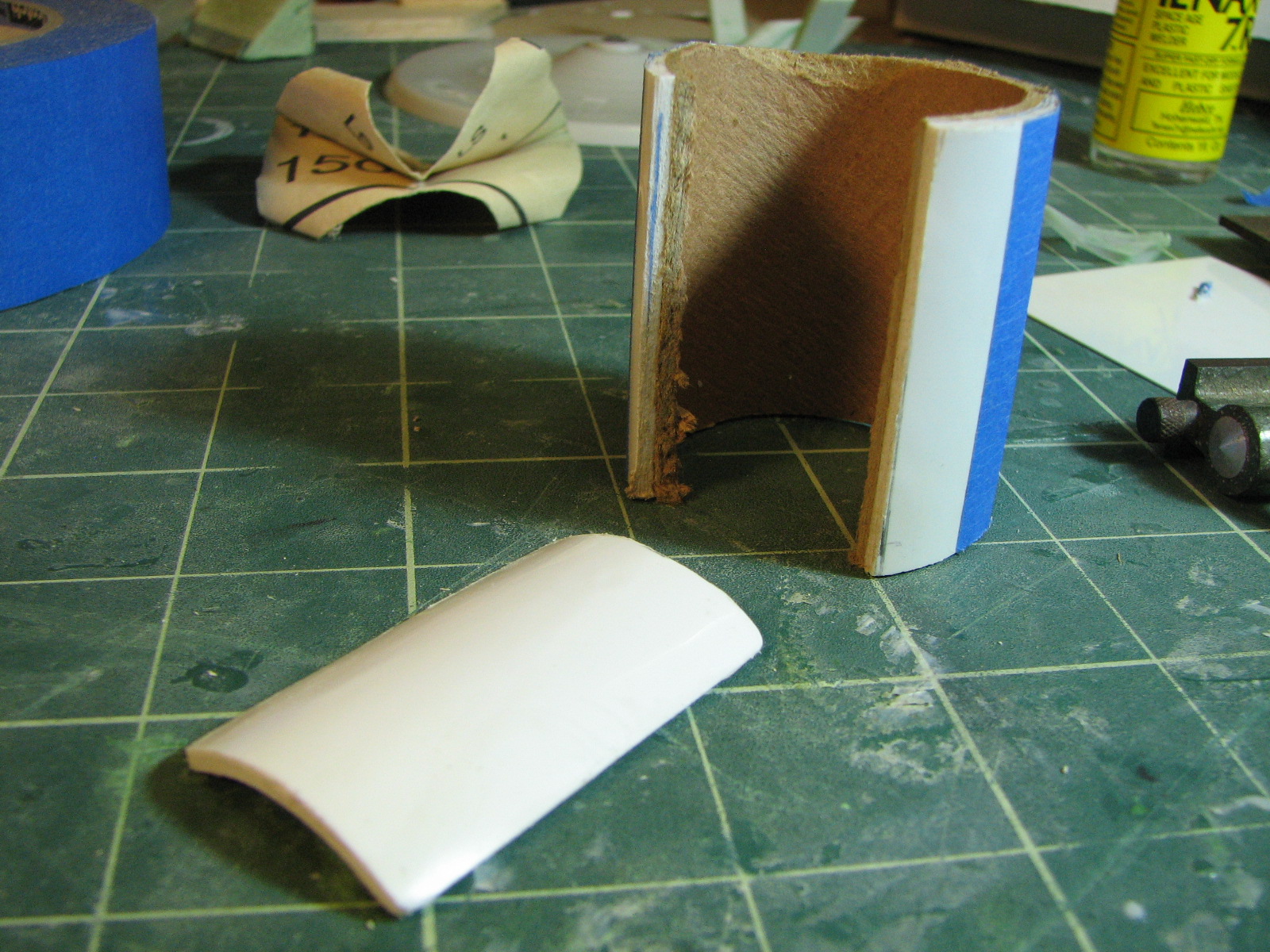
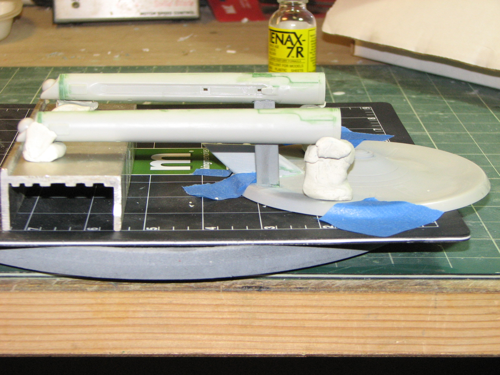
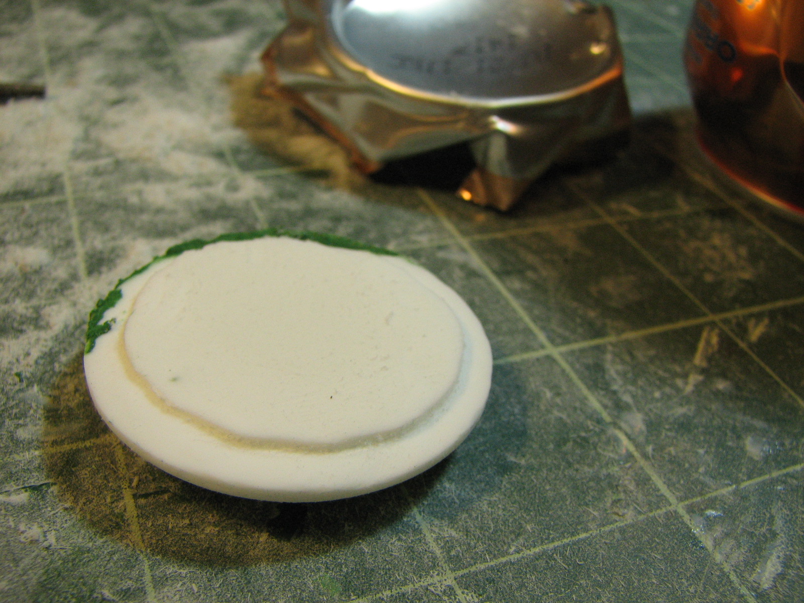
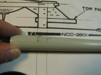
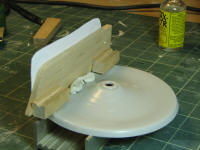
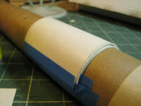
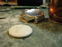
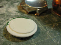
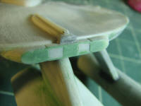
...the tow pad. To make a pad that fits exactly to the
container I laminated 5 sheets of thin styrene together with cement, taping each
sheet around the cardboard tube that formed the container master. After an
overnight drying I cut out a piece the correct dimensions for the tow pad and
cleaned up the edges.

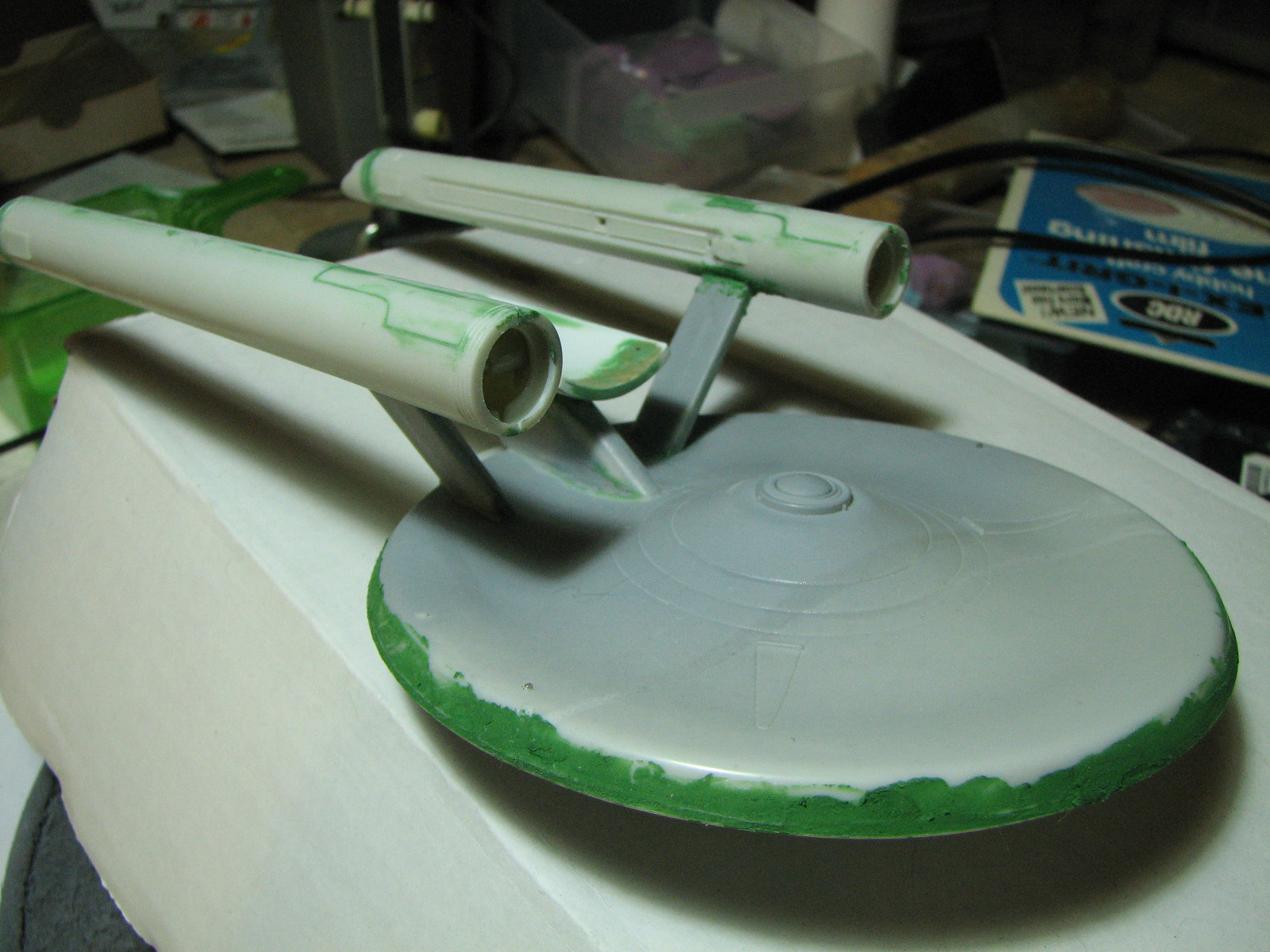
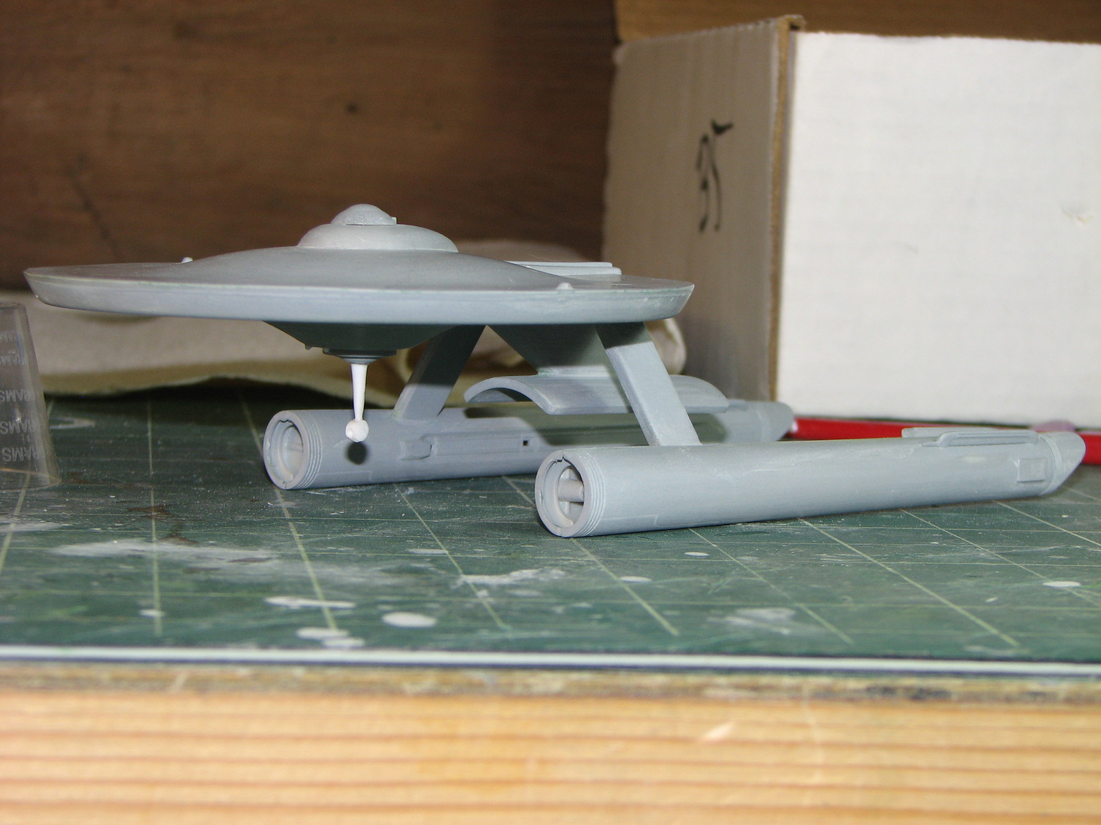
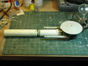
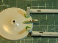
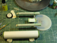
2/2/2011 - This past weekend it started coming together. I
used bits of clay to hold the nacelles in alignment while cementing them in
place. Then I aligned the ship and tow pad against the container master. Cemented!
And now for another round of putty-ups.
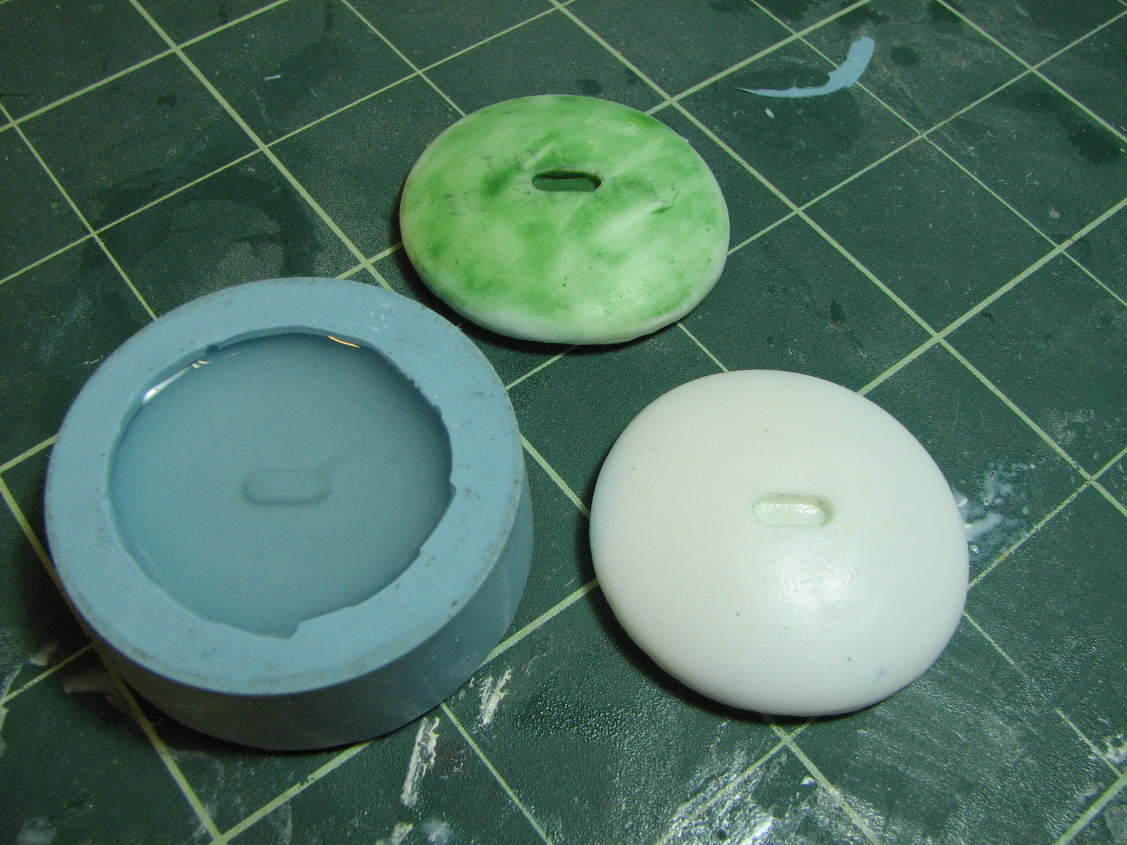
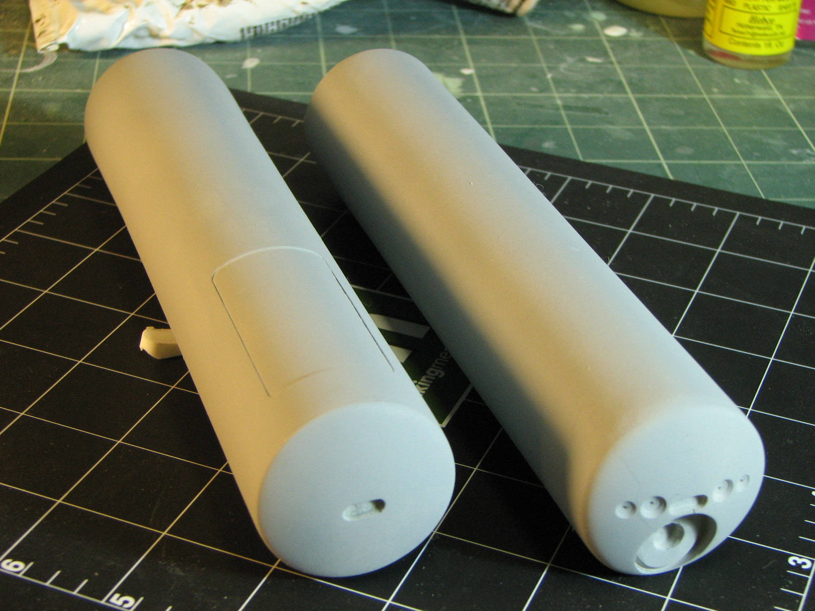
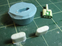
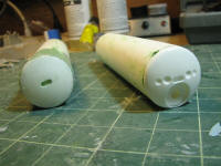
2/4/2011 - On to the transport containers... after I made
the RTV mold from the container cylinder master I made a plaster shell to
provide additional support for it. With a 1.25" piece of vinyl pipe inside the
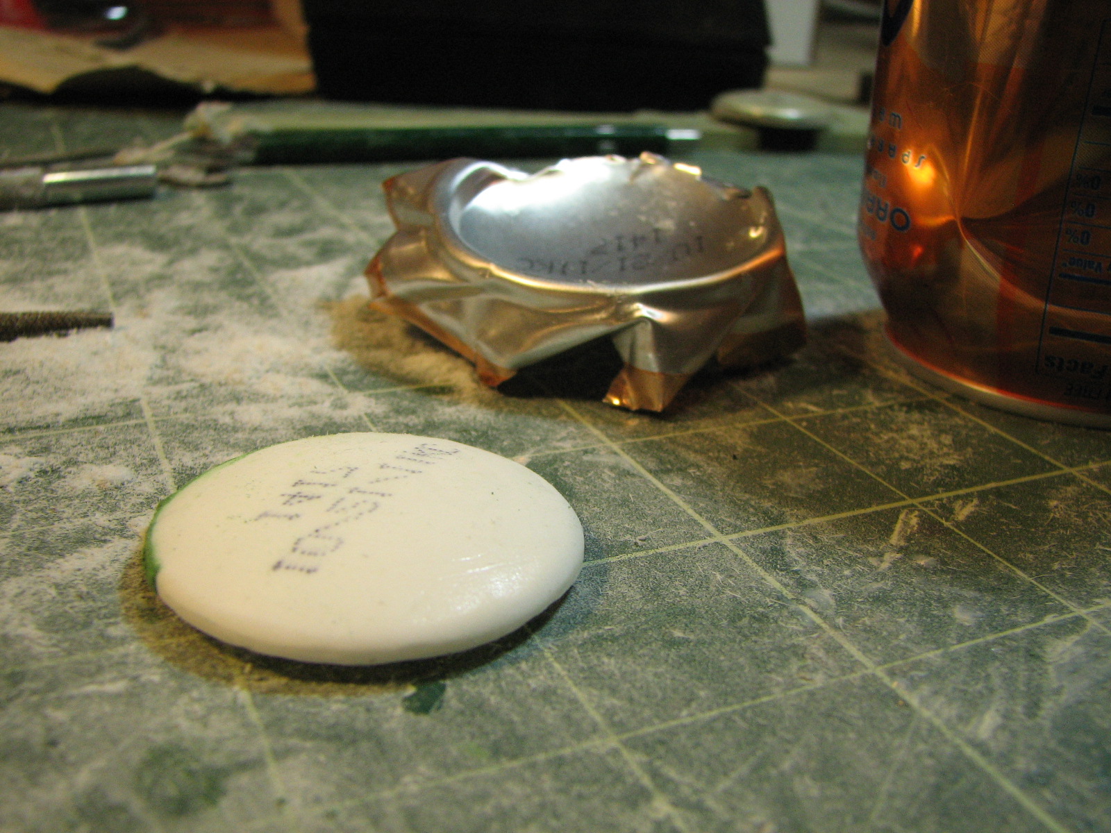
mold I poured a 6-minute A-B polyresin in. I demolded after about an hour. For
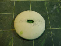
the container ends, I found the indented bottom of a pop can matched the shape
well enough. I had to trim the casting to a slightly smaller diameter and rout
out a lip so the cap would fit into the cylinder. After working the container
gangway / coupler into the piece it will be the master for additional endcaps.
The starliner container endcaps will need additional details for sensors,
deflectors, and thrusters.
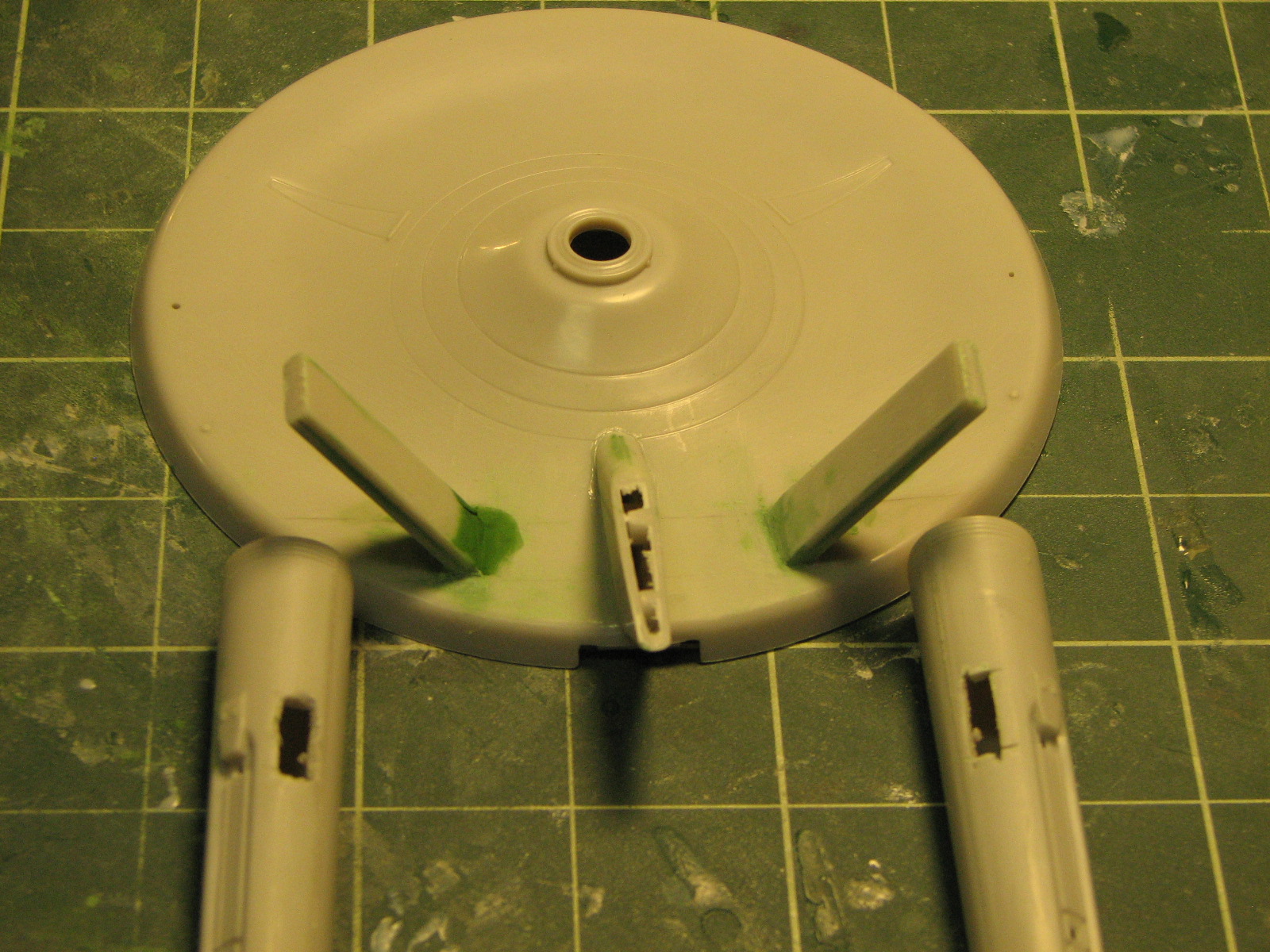
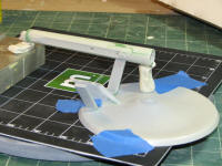
2/7/2011 - With the work done that required being able to
lay the saucer flat upside down, I attached the saucer top to the model and
clamped clamped clamped the heck out of it to minimize seams. Still, it required
a hefty putty job.

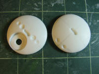
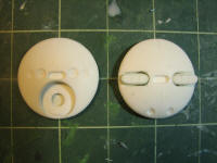
Back to the end caps - I drilled and trimmed out the
gangway opening on the master end-cap, made an RTV mold of it and started with
the castings. The two castings for the "starliner" container (a cargo of
colonists?) require some drilling out for the various sensors and deflectors.
The small dishes were done with a dremel ball bit.
The big dish area... I used an 11/16" spade bit
and variable speed drill to rout this out. Still have
some clean up to do in this.

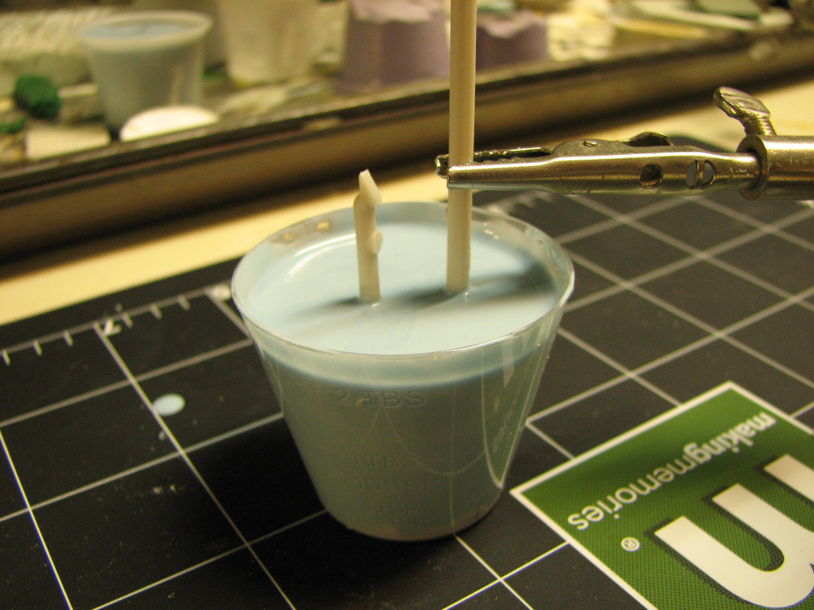
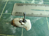
2/8/2011 - Of masters and molds... The deflector arm I
made earlier was just a bit too small so I remade a master for that, and decided
to make the lower end of that a short cylinder, rather than a sphere. They both
look round in side view. I attached that master (made from styrene sprue) to
some other bits of sprue to make a U-shaped master. That went into a 1 ounce cup
of RTV.

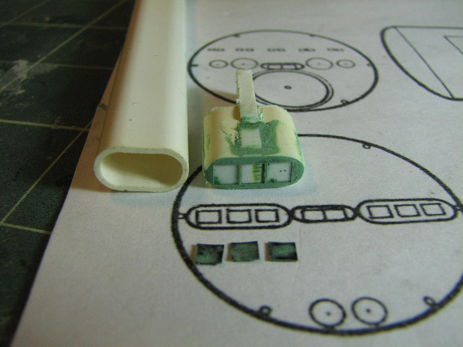
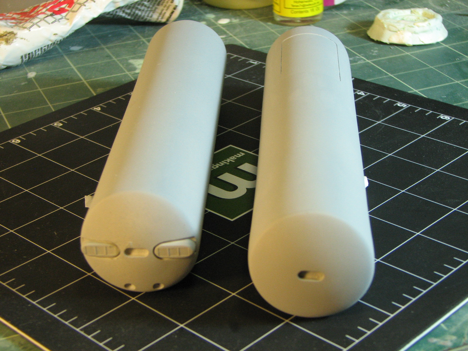
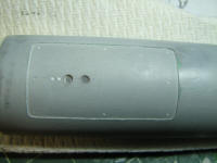
On to the personnel container's aft cap impulse engines...
I used a piece of ovalish tubing as the starting point, which needed to be wider
and shorter. I first cut it apart along the end curves, removed about .05" of
material then glued it back together (the "shorter"). I filled the piece with
resin at this point. Next I cut along the center of the long edge and filled the
gap with a 0.1" thick piece of styrene (the "wider"). After some putty and
sanding, I placed 3 small squares of black vinyl tape on the end, where the
impulse exhausts are. I puttied over the whole end, let the putty dry overnight,
then sanded down to the black tape and peeled away the tape, leaving small
insets. This master got an RTV dunk too, after first painting RTV over the
exhaust insets to avoid trapping bubbles. I made two castings from this mold.
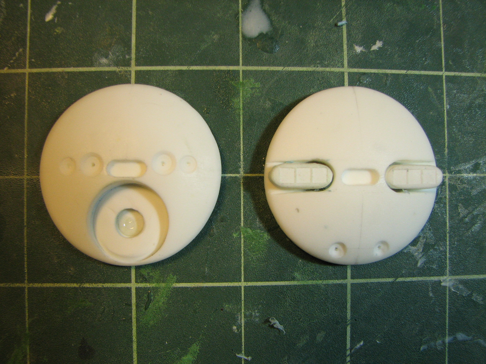
2/10/2011 - Still having trouble getting good antenna
armatures. But the endcaps for the passenger container are finished. I drill and
filed out openings for the impulse engine on the aft end cap, cut down the
engine pieces so they fit flush to the surface of the cap and superglued them in
place. I pulled molds off these in case I should ever need to make more.
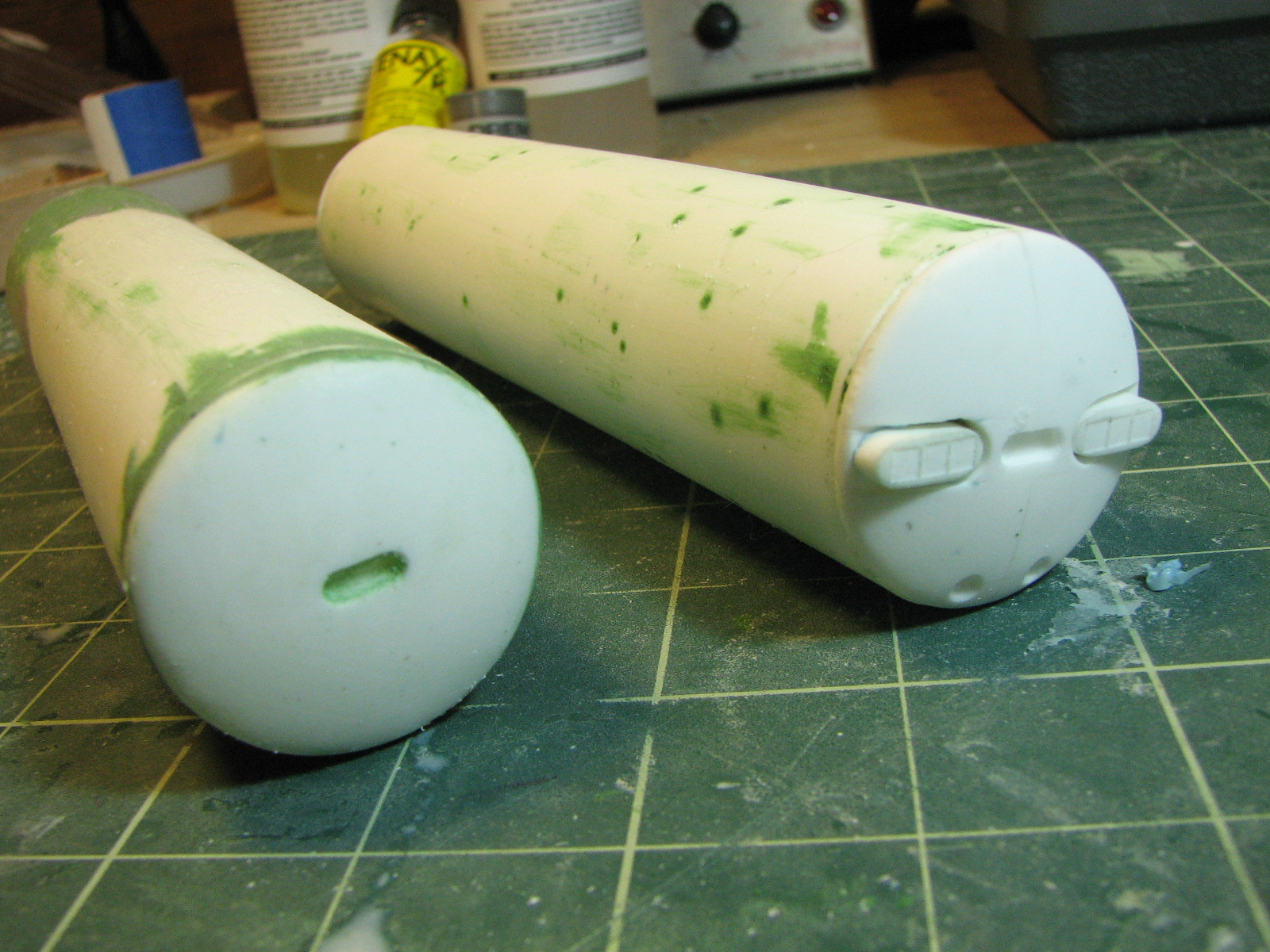
I superglued the endcaps to the container bodies and
started with puttying up the seams.

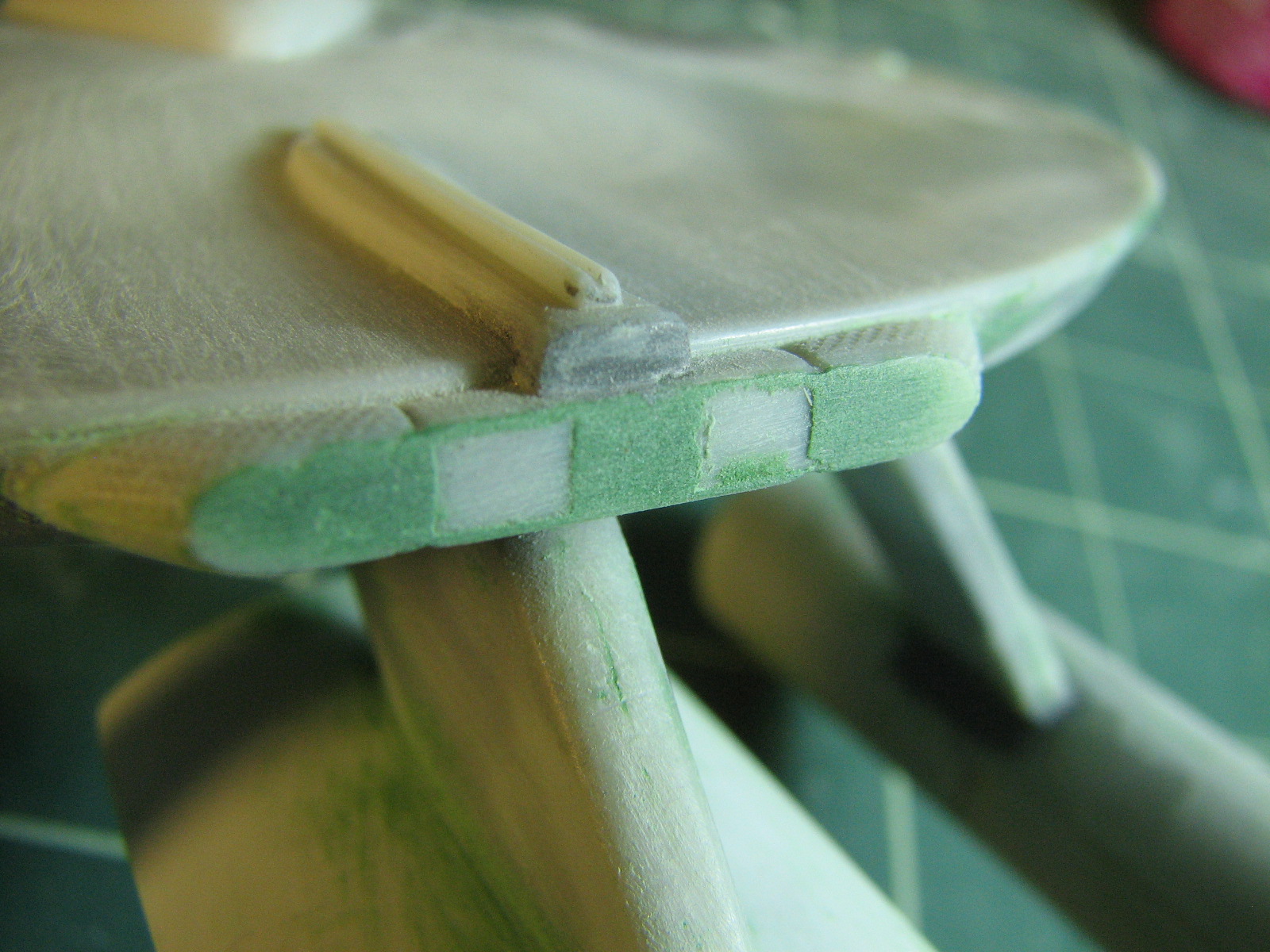
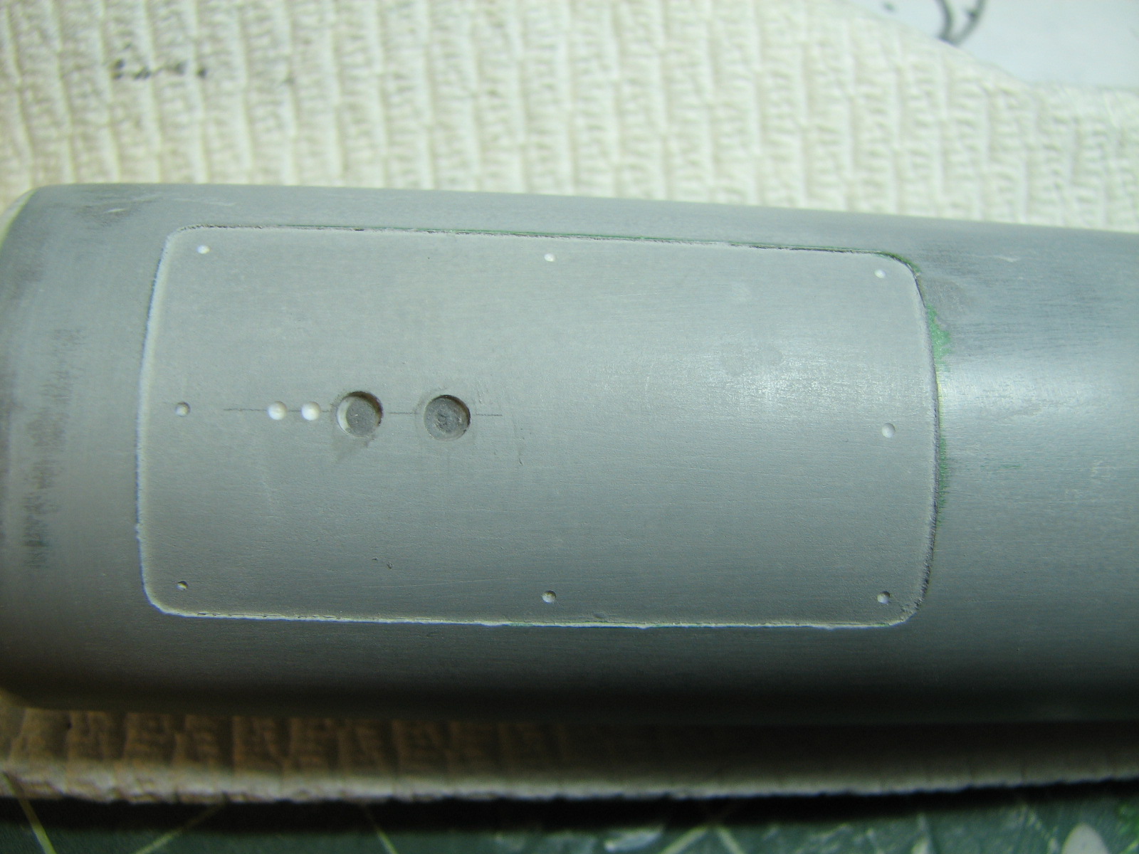
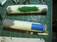
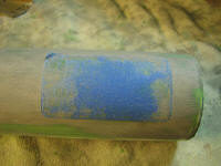
2/14/2011 - To make insets for hatches, the towpad, and
starship impulse engines I used the same tape & putty methods as for the
personnel container impulse engine master. On the towpad I used 3x thickness of
blue painter tape. The gray putty used here is automotive glazing putty. Once
the putty had dried I wet-sanded it level with the tape, touched up the putty...
repeated until the putty was smooth and feathered out to the white resin
surface.
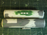
Finally... a coat of gray automotive primer.


2/15/2011 - After installing the deflector armature, this
went to priming. It has a coat of automotive gray on it now. The whole project
is here.
3/1/2011 - Getting down to the fussy work leading up to
painting. I added phaser blisters to the transport, 2 topside aft, 2 low on the
front underside

One other remaining detail was to add some turbo lift
hatches to the cargo pod. I also added some umbilical connects and latch
sockets.
Finally it's on to painting, which is on the whole project
page here.