|

Blue Moon's
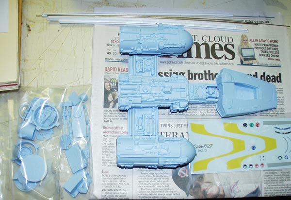
"Wishbone" Fighter
I wonder what
that name refers to...
Wishbone
Parts
|
 |
|
Stated scale:
|
1/48
|
 
|
|
Actual scale:
|
unverified
|


|
|
Overall length:
|
|
|
Material(s):
|
resin, metal, styrene
|
|
Number of parts:
|
26 resin + wire and T stock
|
|
Stand included?
|
no
|
|
Decals included?
|
yes
|
|
My Source:
|
Starship Modeler
|
|
Cost (w/o s&h):
|
|

11/27/2007
On a whim, I pulled this off the shelf and started
cleaning up the resin flash and other irregularities. There aren't many. I
assembled the vectoring rings and exhaust assemblies using superglue, and
installed the cockpit bucket and instruments. Also attached the aft and top-aft
detail pieces to the main body.
12/1/2007
Snowstorm Day! Perfect for watching movies and building
kits.
I attached the engine mount crosspiece with 5-min epoxy
and drilled holes for aluminum reinforcing pins in the main body, droid module,
and cockpit module.


I assembled those three modules with 5-min epoxy. No,
really, they are all ortho - just an oddity of the camera lens below.

12/5/07 - More drilling, more metal pins... the engines are epoxied
on.


The kit includes styrene T-stock to connect from the
engine modules to the vectoring assembly (VA). Call me wacko, but I'd like to
get some metal stock for that instead (success! see below). I've started cutting little T-grooves
into the attachment surfaces on the engines and VAs so there's a better
connection for the T-stock.
| 12/15/07 - Off and on
puttying / filing / sanding have been the order of biz on this model
recently. I've gotten the engine exhaust pieces close to done. I added a
collar of 0.2" wide styrene around each to fill and cover gaps. From the
look of shots in the ILM Model Shop book, the inset areas under the cone
between the flanges should have detail chunks piled in there. I'll add
styrene and parts box chunks to fill that out.
I also added various-thickness styrene shims to
the aft recesses of the engine pods where the exhausts fit in. The depth
of these ranged 0.39" to 0.45" (portside) and 0.44" to 0.52" (stbdside).
The shims range from 0.01" to 0.17" and make it so the exhausts all fit
to the same 0.39" depth all around. |
 |

12/22/07 - The off and on puttying / filling / filing /
sanding continues. I found some brass T-stock to replace the styrene stock.
Special Shapes makes it in 36"
lengths; I found it at Hub Hobby in the Twin Cities.
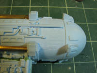
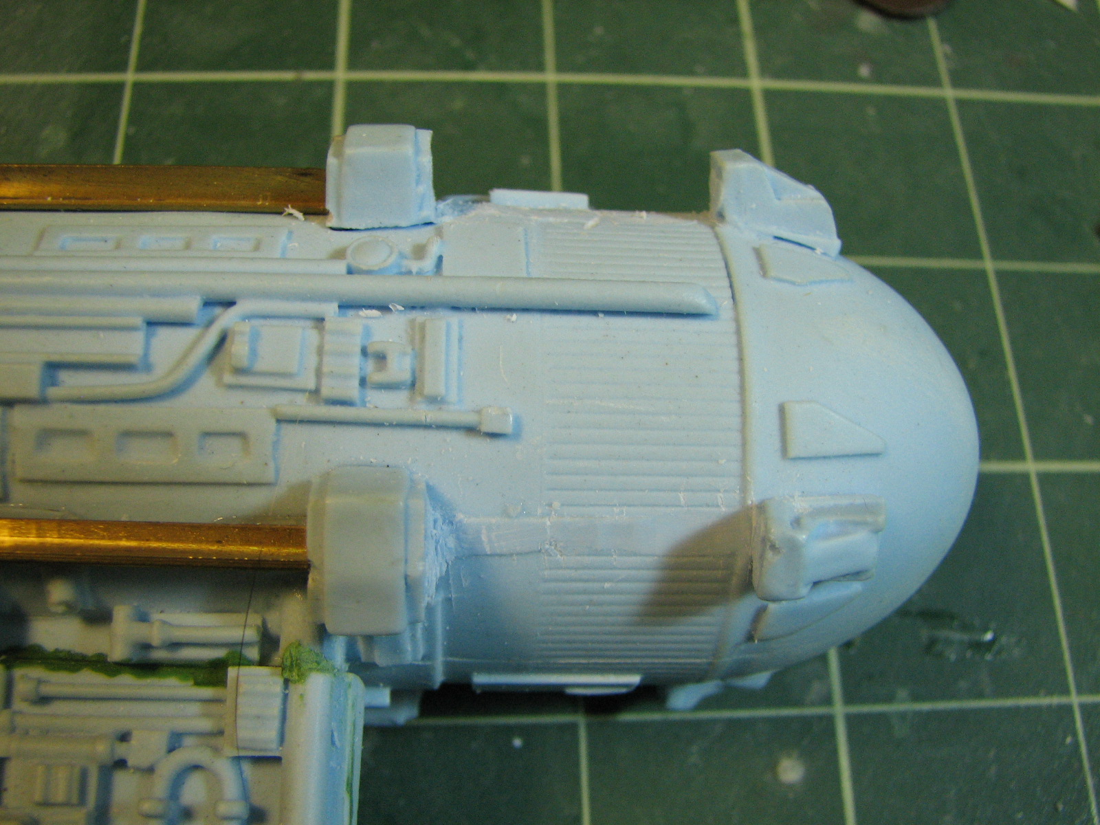
1/6/08 - I primed the engines and engine wells before
epoxying the engines in place. Note the detail added to the engine piece forward
of the exhaust cowl. This is styrene strip stock in half-round, rectangle, and H
shapes. And while I was at it I primed the cockpit tub too.


1/11/08 - I used a bandsaw to cut the brass T-stock to the
proper length.

I began by attaching one strut to each engine using
superglue. I scored a small T into the resin at the fore end of the strut so it
would have a bit of something to grab onto. I aligned the struts parallel to
engraved detail lines on the engine and did a whole bunch of eyeballing.

I also scored a T into the rudder housings for the aft
attachment point of the struts. I tried using rubber bands to hold all the
struts on an engine in place and aligning them before gluing them down, but that
proved too unwieldy. So I glued things on each engine in this order:
2. Struts 180° around from the first strut.
3. Attached rudder housing to the two struts, carefully aligned them and then
glued.
4 & 5. Dry-fit the other two struts into the engraved Ts and then superglued
them down.
In a few cases I had to flex the brass a bit to get a good fit to the housings.
I still need to putty in and around the brass-to-resin attachment points.

1/16/08 - That one little nagging thing finally nagged me
into action. Those detail areas fore of the brass struts are one place where the
kit could have benefited from having more parts. I'm going to make a set of
parts to replace the muddy detail here between the banded rod thingies. Each
area will have two of these rods flanking a short piece of 1/8" T-stock.
 |
 |
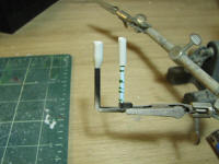
| I sawed out
one of these areas (top of image at right) and trimmed away resin from
the sawed-out piece until I had isolated a banded rod (bottom of image
at right). I puttied over the trimmed surfaces to begin rebuilding the
banding detail on the rod. So, now it's off
to the molding/casting bench...
|
| 1/20/08 - Just
call me Bender Bending Rodriguez. Last night's
'fun' included sizing and bending the piping bits for the Ywing. I
started out just bending and sizing to match the illos on the sheet.
But...when I test fit #1...
oh... those aren't full-scale illos. Good thing the 3/64" piece they
included was longer than necessary. OTOH, the
single piece of 1/16" stock they included
wasn't quite enough to get all the larger pipes done, so I scrounged for
some - all I had was some steel clothes hanger
stuff. Yeah... fun to cut and bend. So that's why #s 6 and 7 look non
brassy. I'll be painting the
piping separately and adding them after the rest of the thing is
painted. |
 |
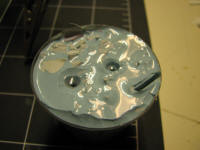
2/7/2011 - hmm... 3 years this had been on the shelf,
untouched. I thought I'd make up a mold so whenever I have some extra resin from
another casting (which at this point happens to be the
Franz Joseph
Transport container parts), I can cast a replacement strut for that muddy detail on the
engines. I first tried this just making a mold of the strut by itself, but that
was prone to having air bubbles stay in the mold and making incomplete castings.
So, I made a U-shaped master where I can pour resin into one hole that will flow
down and fill the strut mold from the bottom up and force air out. That master
is a cleaned up strut super-glued to some styrene sprue. I poured RTV around
that, then cut the mold open to remove the master. Castings from this are
bubble-free. I had at the muddy detail with nippers and x-acto to clean out
those 8 areas in prep for the new detail pieces to go in.

