


|
|
|
|
|
|
|
|
|
Discovery OneLunar Models |
 |
||
|
Stated scale: |
1/211 |
|
|
|
Actual scale: |
unverified |
|
|
|
Overall length: |
32" |
||
|
Material(s): |
resin, brass |
||
|
Number of parts: |
100+ |
||
|
Stand included? |
no |
||
|
Decals included? |
no |
||
|
My Source: |
Lunar Models |
||
|
Cost (w/o s&h): |
US$ 165 |
||

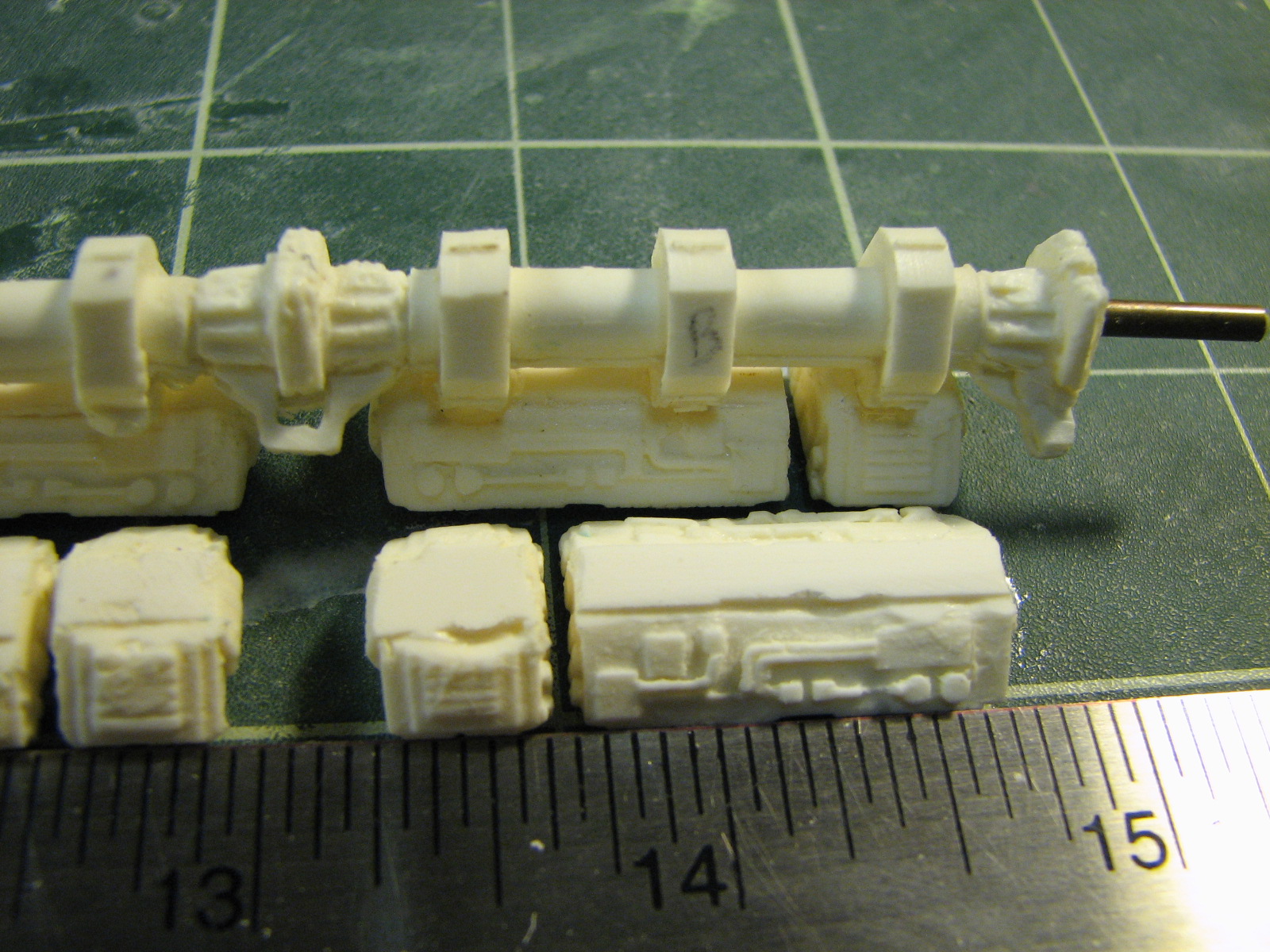
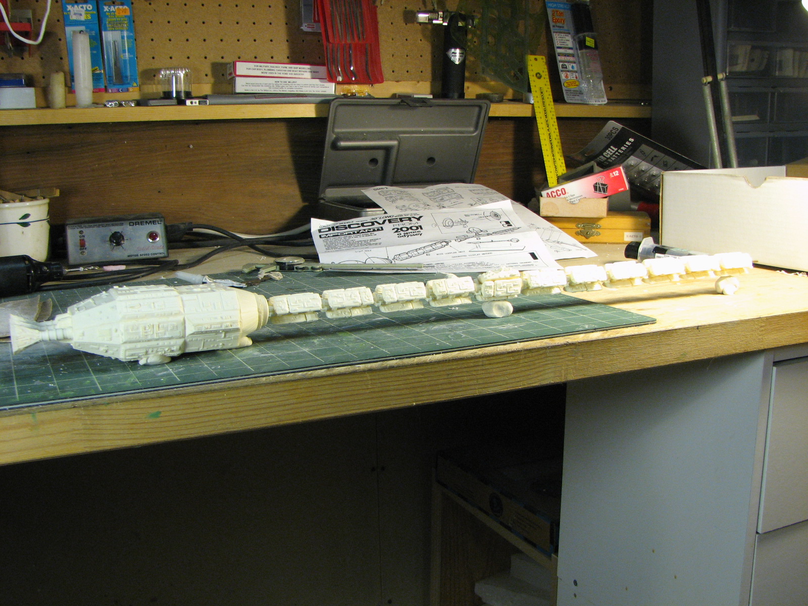
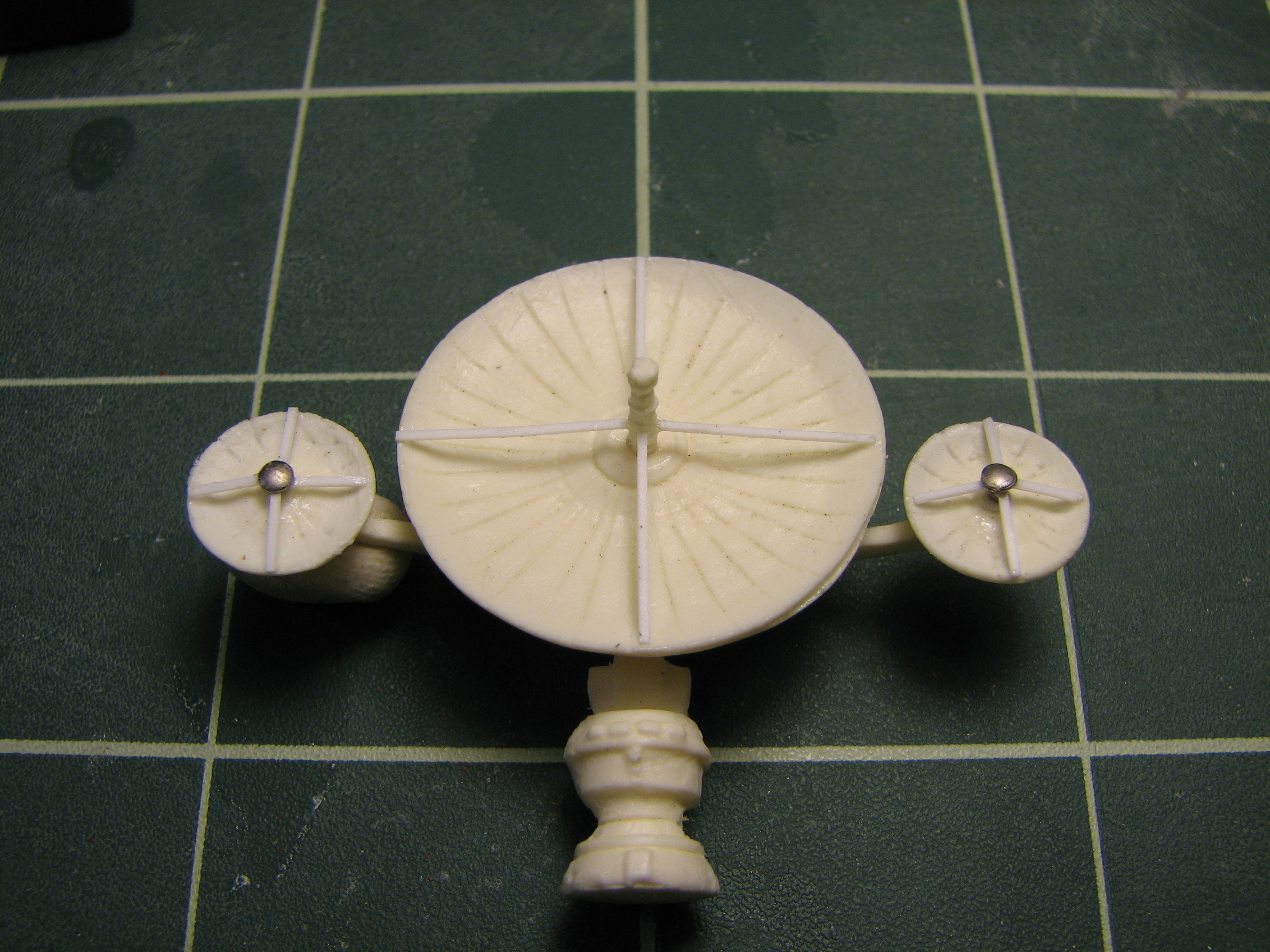
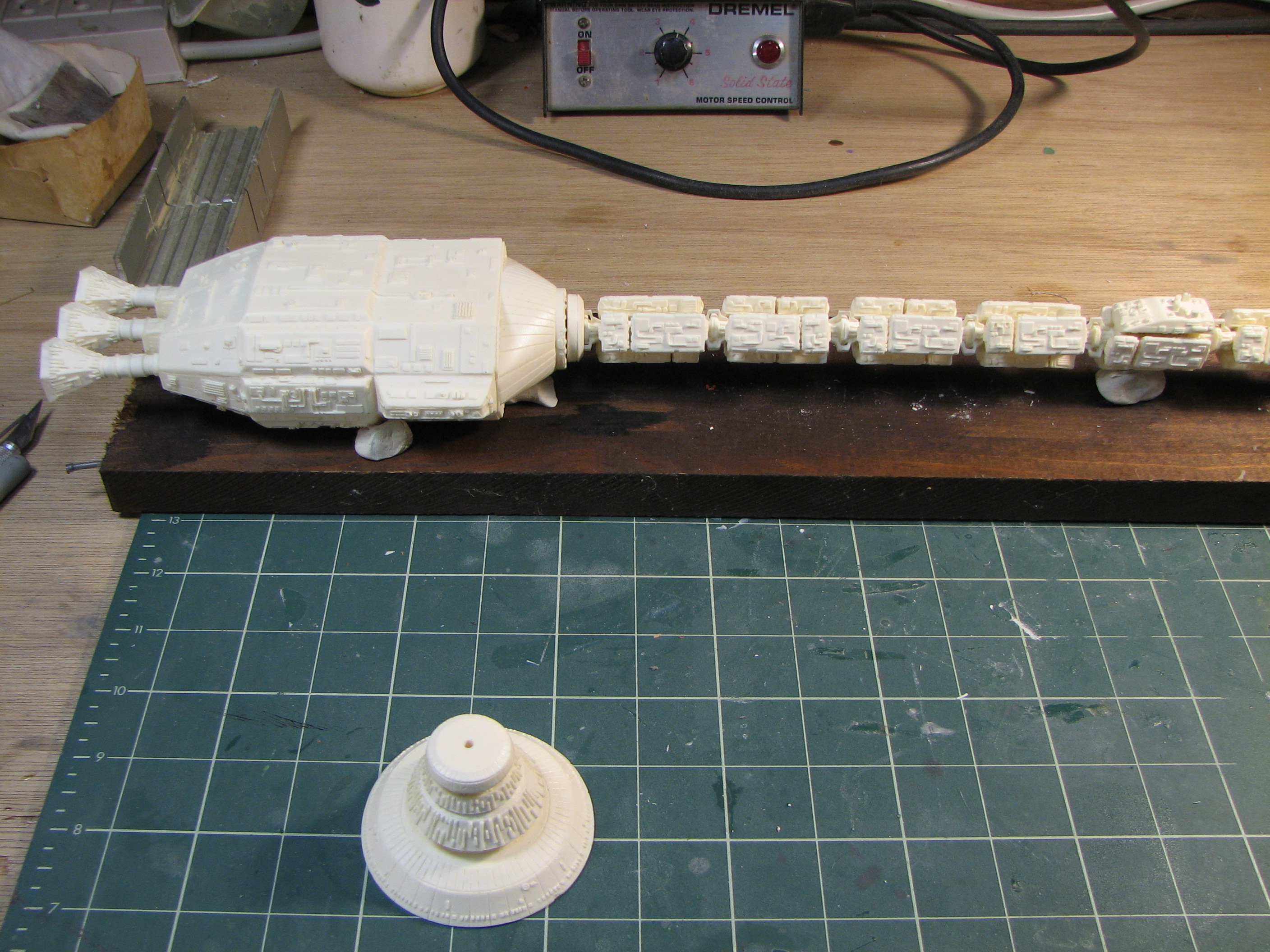
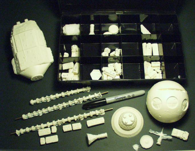
1/4/2010 - Well finally, 10 years late. I've assembled the antenna dish sub-assembly and prepped the engines for attachment to the engine module. Sometime between now and many years ago (maybe 2001?) I cleaned up the multitude of assorted small parts and fuel modules - sorted them out to match the module components up when they get arranged along the spine pieces.
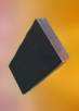
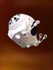
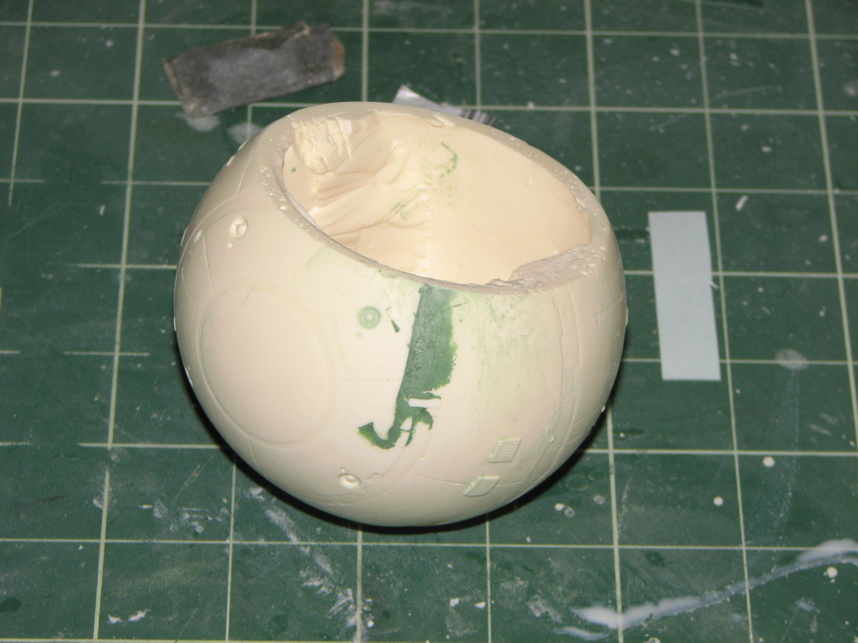
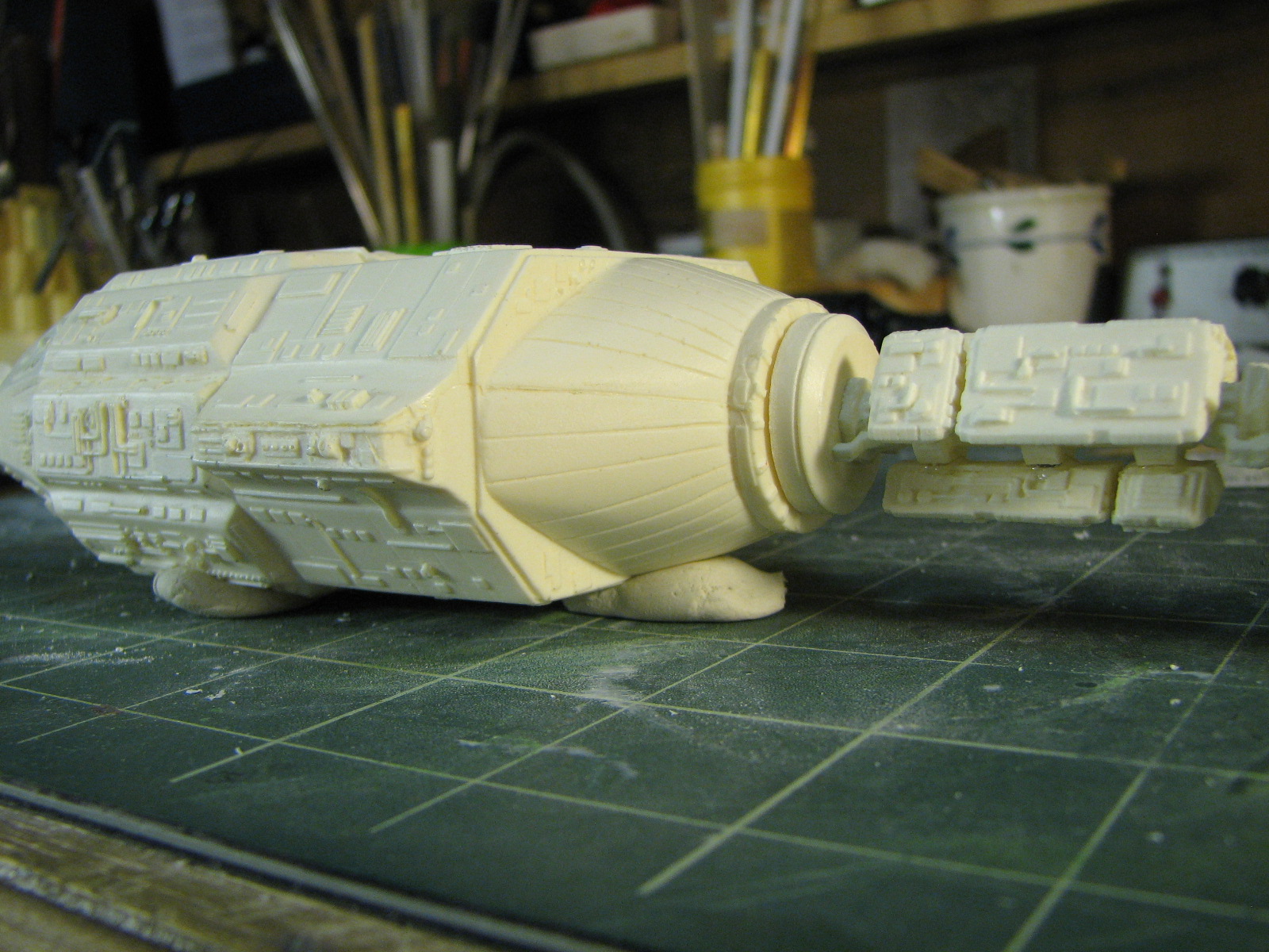
The habitat sphere had some mold mismatch edges on both sides that needed puttying.

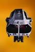
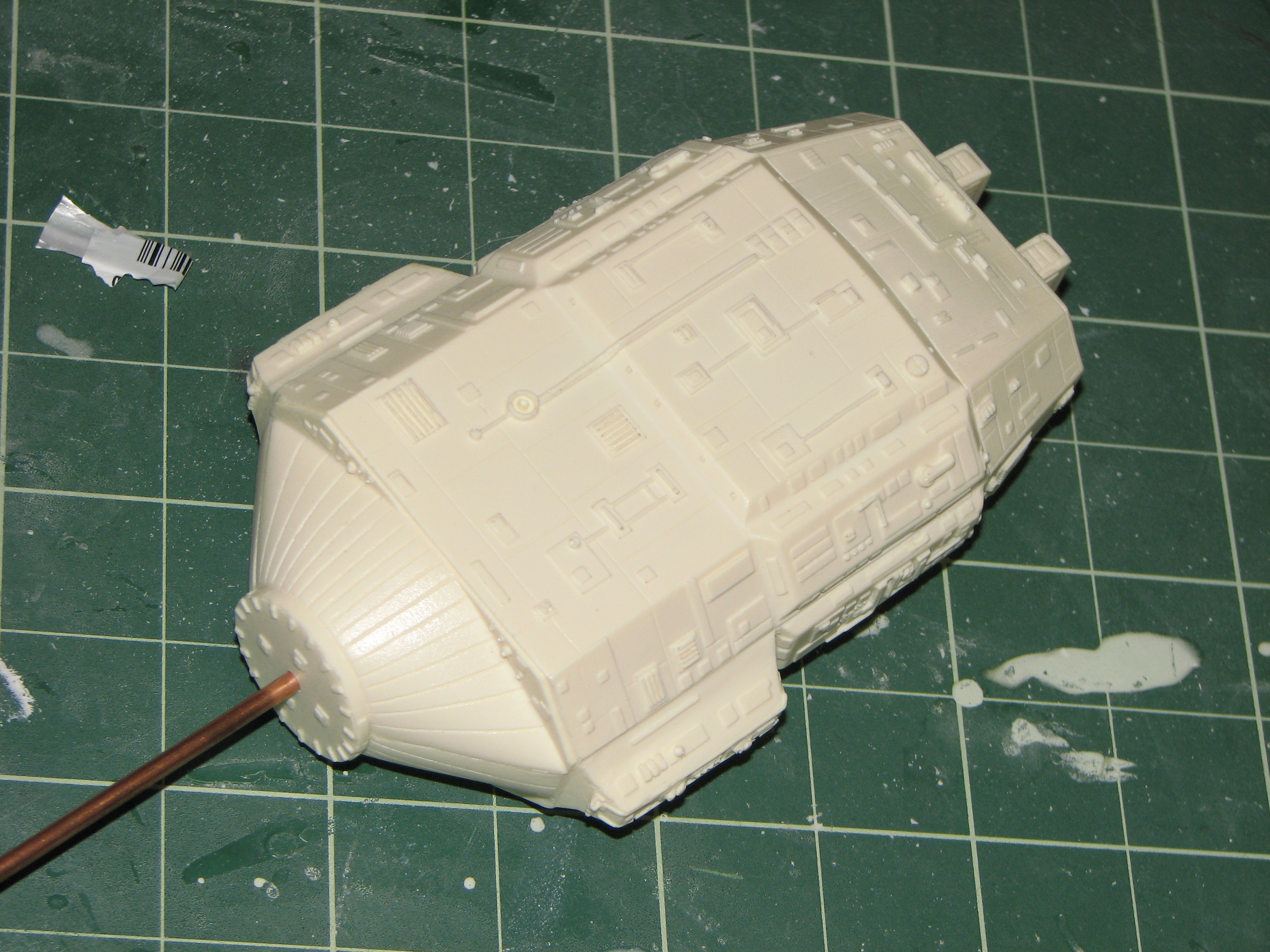
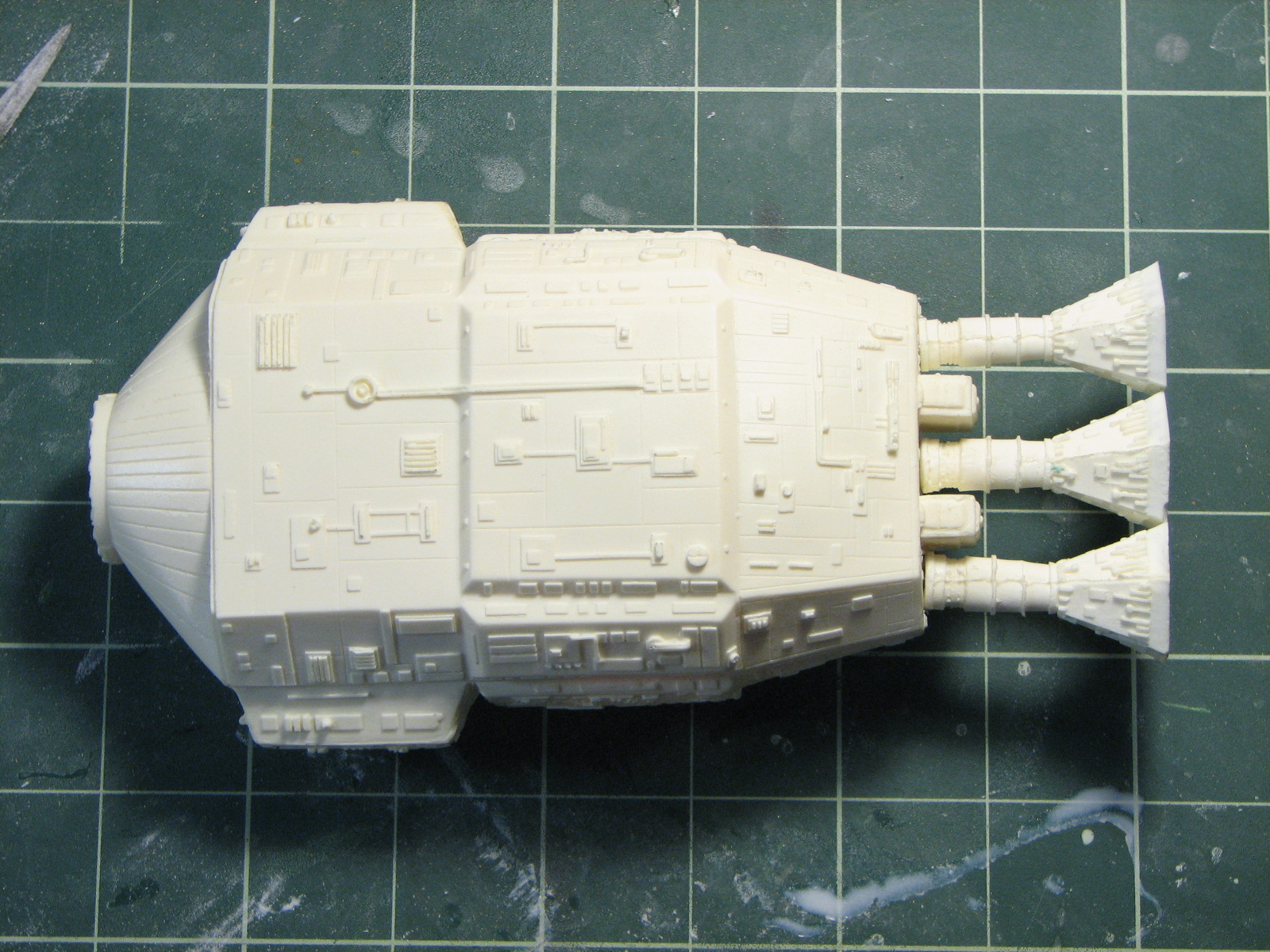
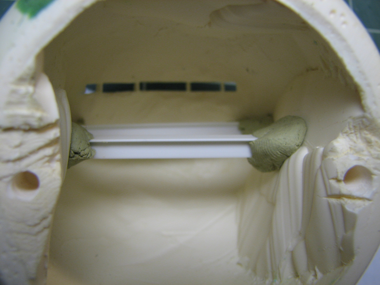
1/14/2010 - Attached the thrusters to the engine reactor module. I fed 1/8" tubing through the reactor (front to after-center thruster location) and made pins for the thrusters from 3/32" brass wire. CAglued the thrusters into 3/32" holes drilled in the module, and into the 1/8" tubing.
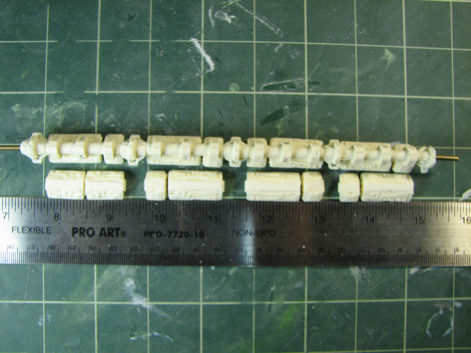
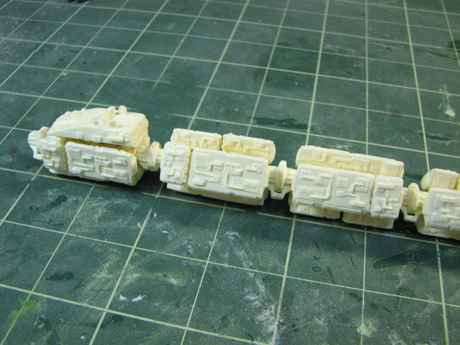
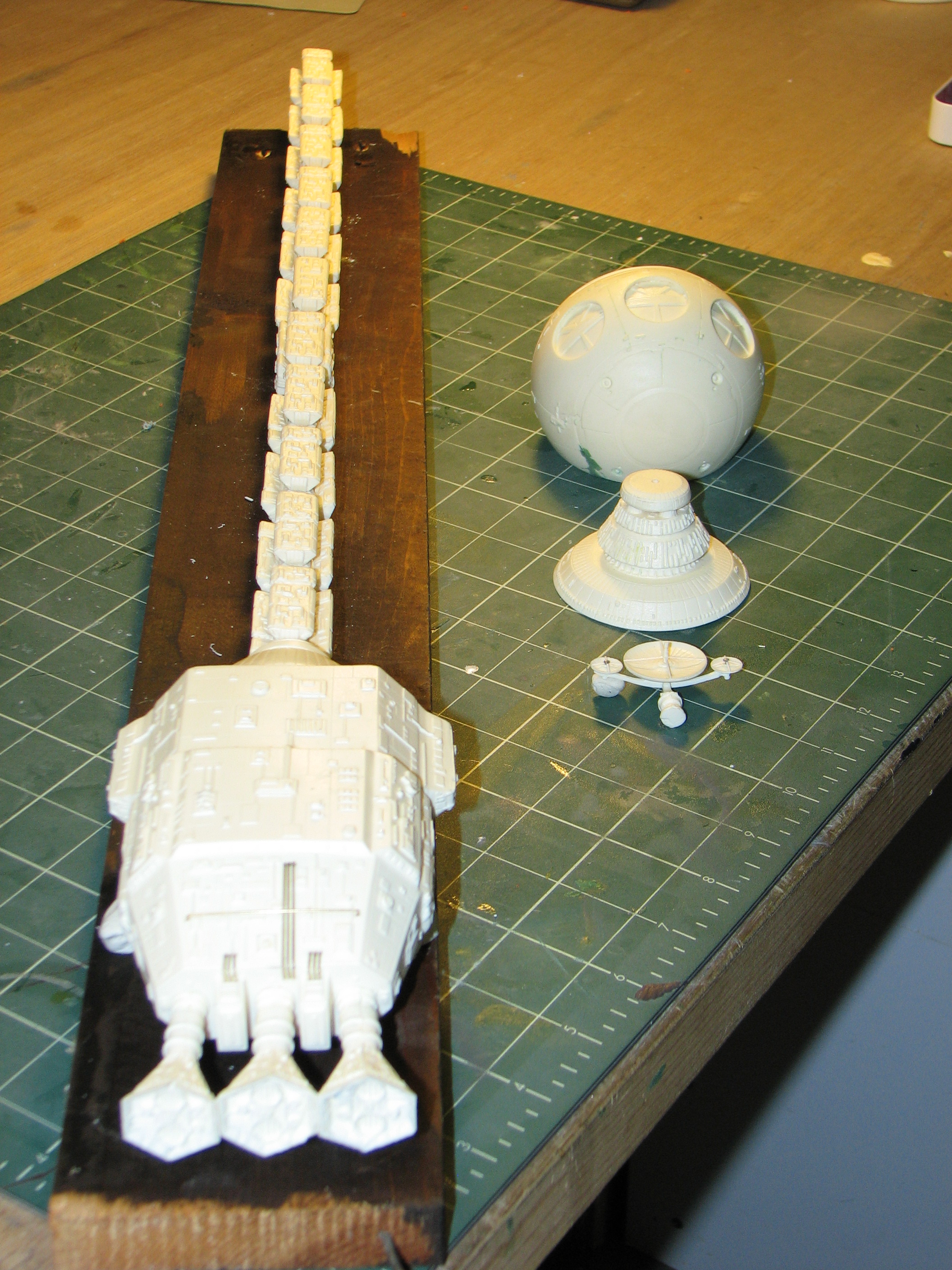
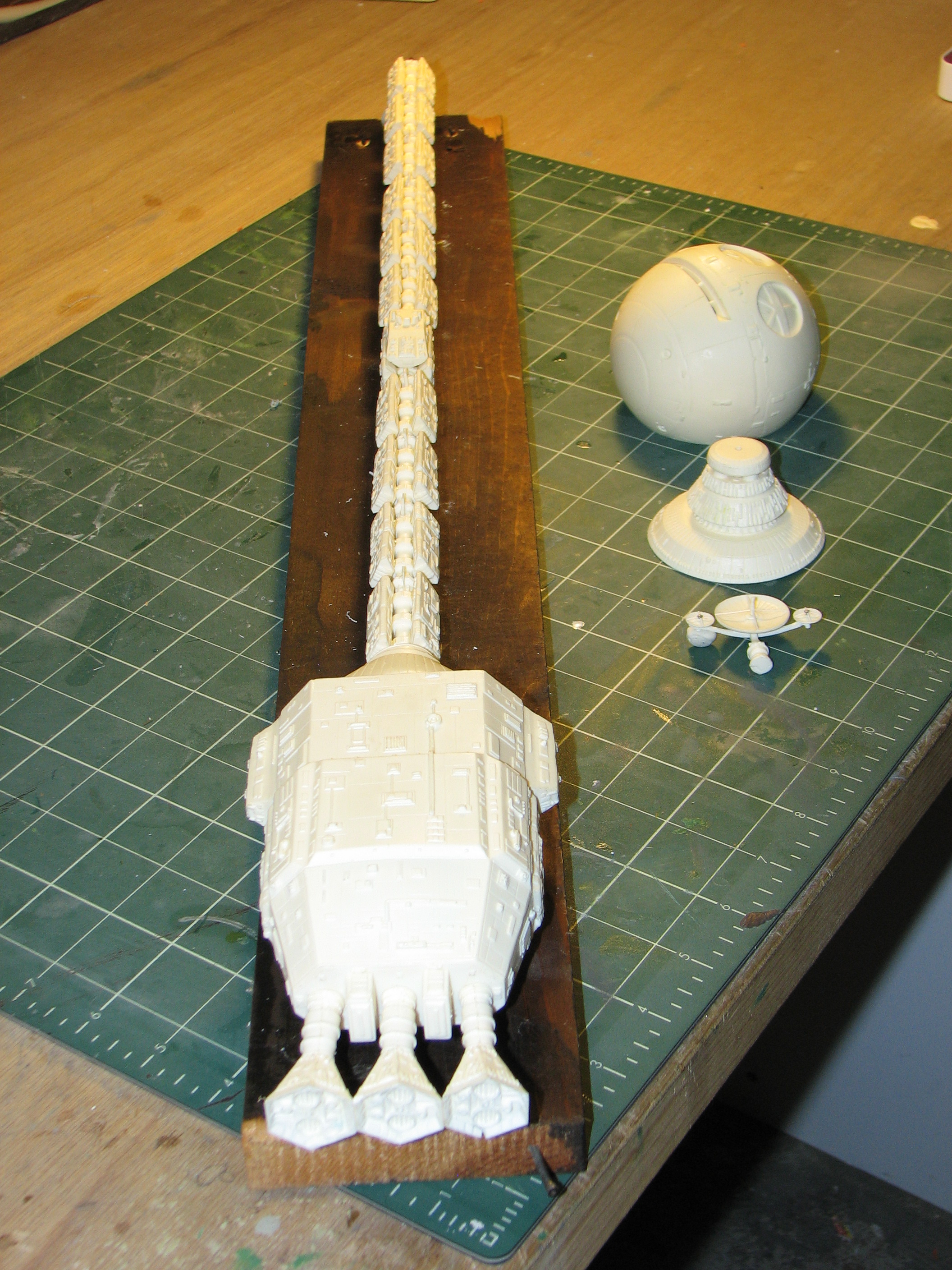
2/26/2010 - Spine Day! The spine of the ship is in three sections. The fore and aft sections each bear 4 module clusters; the center section bears the antenna cluster and two other clusters. Starting with the forward section I carefully lined up the module sections, put drops of 5-minute epoxy on the spine-module attachment points and lowered away. Once the epoxy had gelled, I made any adjustments needed and let the epoxy set up fully. I repeated this for the other two lines of modules around the segment. (That assembly took the better part of an hour.) I tagged each spine segment with a bit of blue tape to keep track of the correct orientation of the segments. Cuz you know, somewhere out there would be someone just checking to make sure I didn't get the gamma-3 modules reversed or swapped for the beta-3 modules.
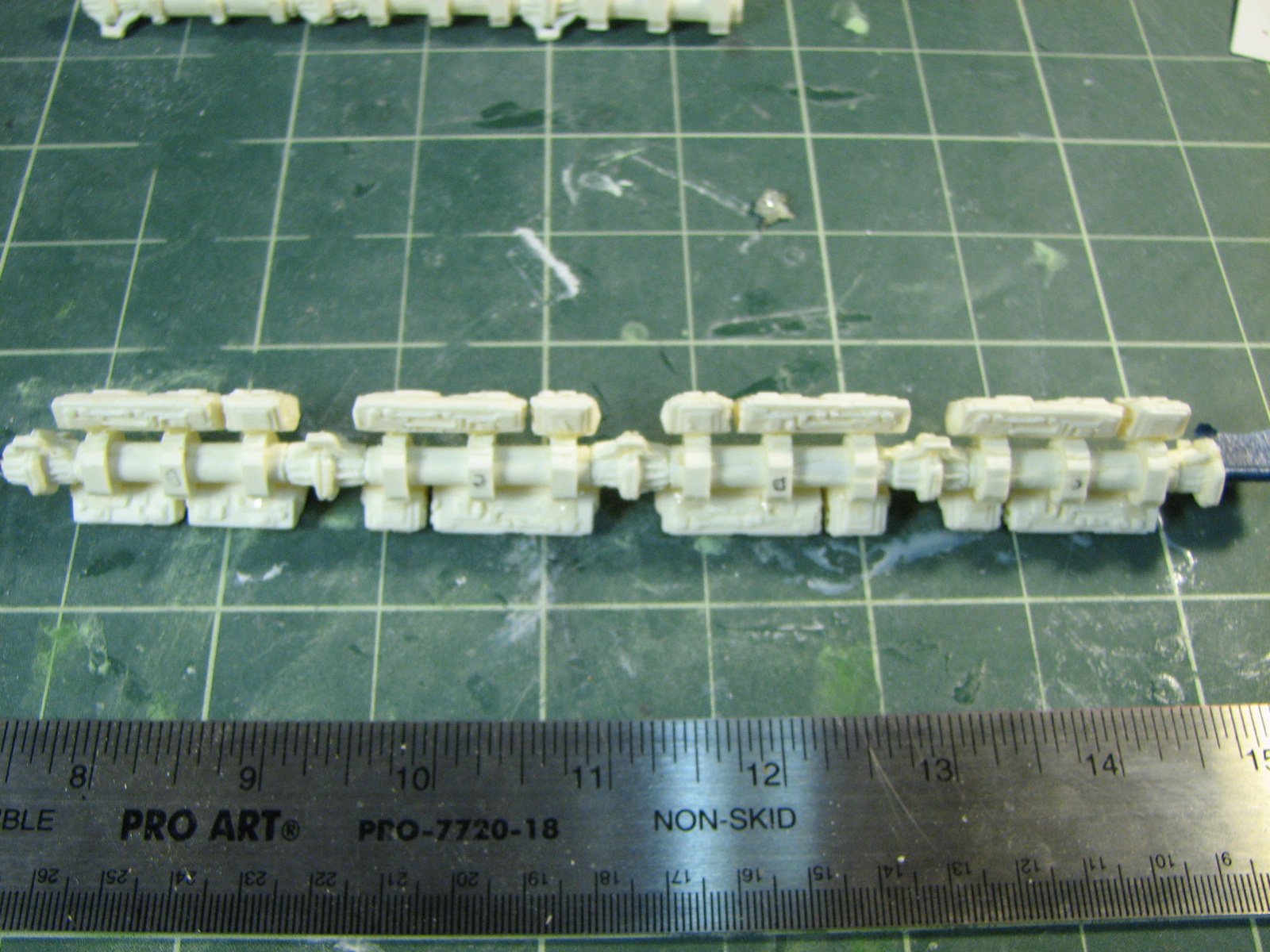
Next, I attached the bottom row of modules to the center section, then attached that section to the fore section, ensuring that the modules lined up. I worked around the center section for the two module cluster fore of the antenna, then added the antenna cluster modules.
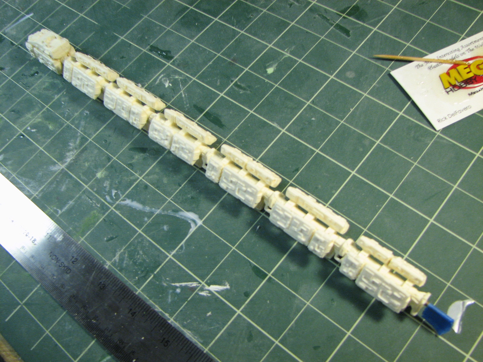
Finally, I assembled the aft spine section, again attaching the bottom row of modules, attaching the section to the spine, then working around it to attach the other module rows.
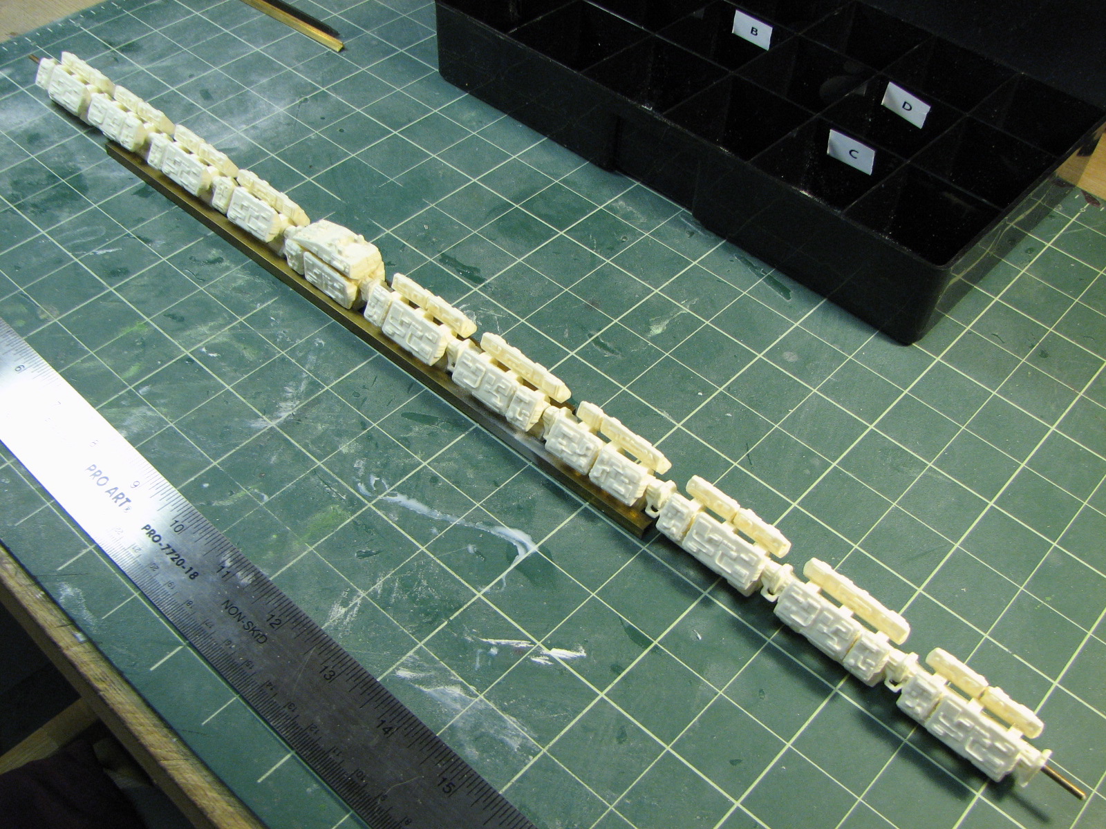
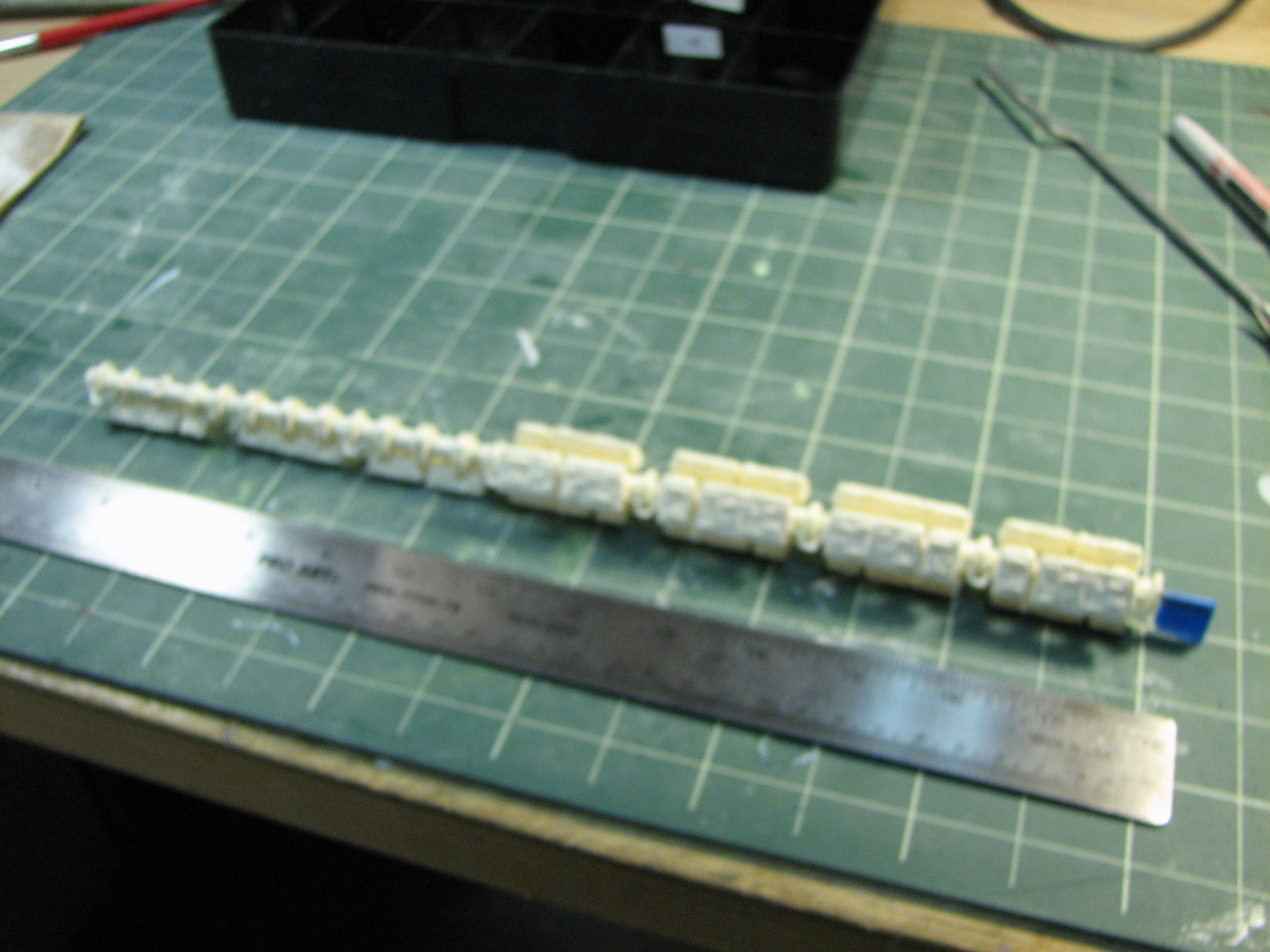
2/28/2010 - I let the assembly cure overnight, then attached the spine to the engine module. I set the engine module and spine on clay blobs to level them and hold them in place while the epoxy set.
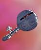
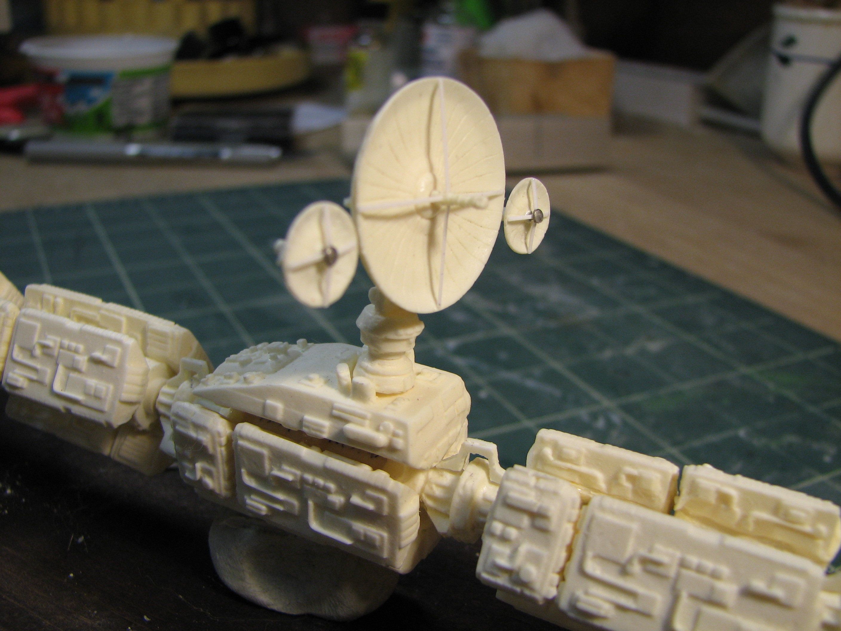
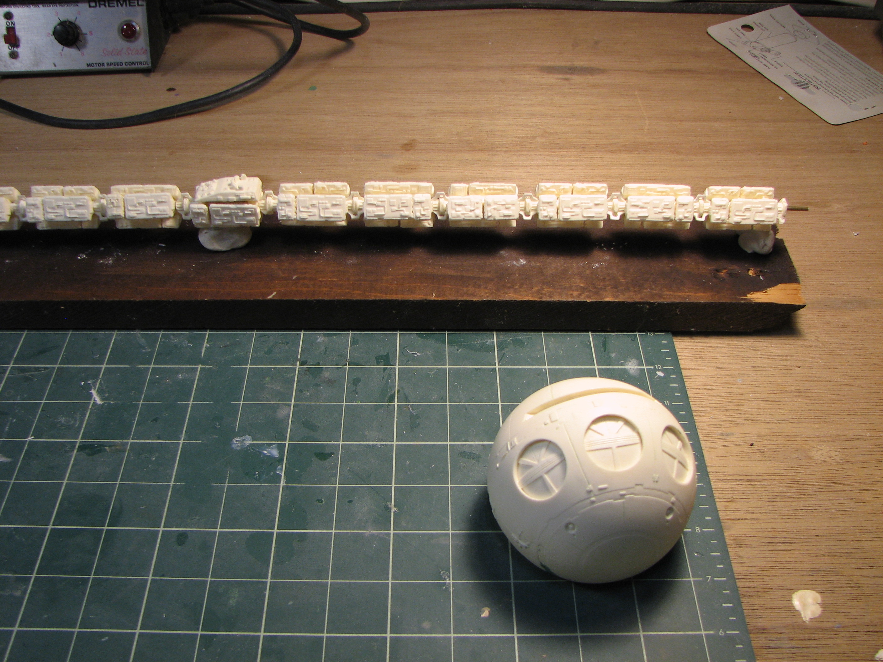
9/6/2010 - That epoxy should be set by now... This became the Labor Day weekend project. I started by finishing the antenna assembly. I added the main dish center spike. The kit made no provision for the aux dishes' center spikes, which are sort of mushroom shaped. I cut the heads off 2 straight pins and glued them to the dishes. All 3 dishes, not just the center one had support rods for the spikes. I glued in pieces of .01x.02" strip styrene.
Next up, the 10 spine dorsal couplers and 2 half-couplers. The kit only had 8 pieces of couplers so I made a quickie clay mold and cast some extra from poly-resin. I glued the 10 spine couplers and aft half-coupler in place. The fore half-coupler will wait until I attach the habitat module.

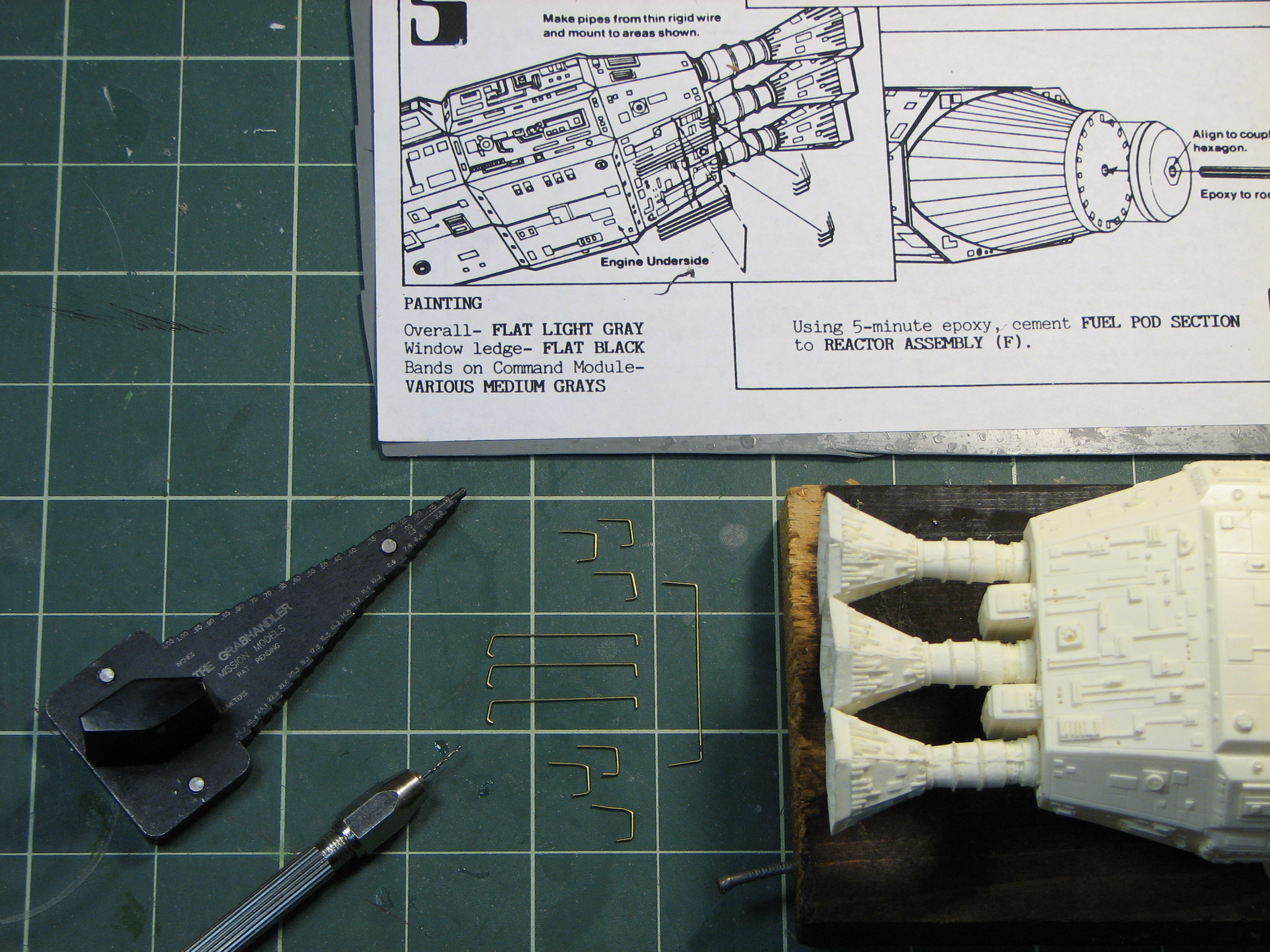
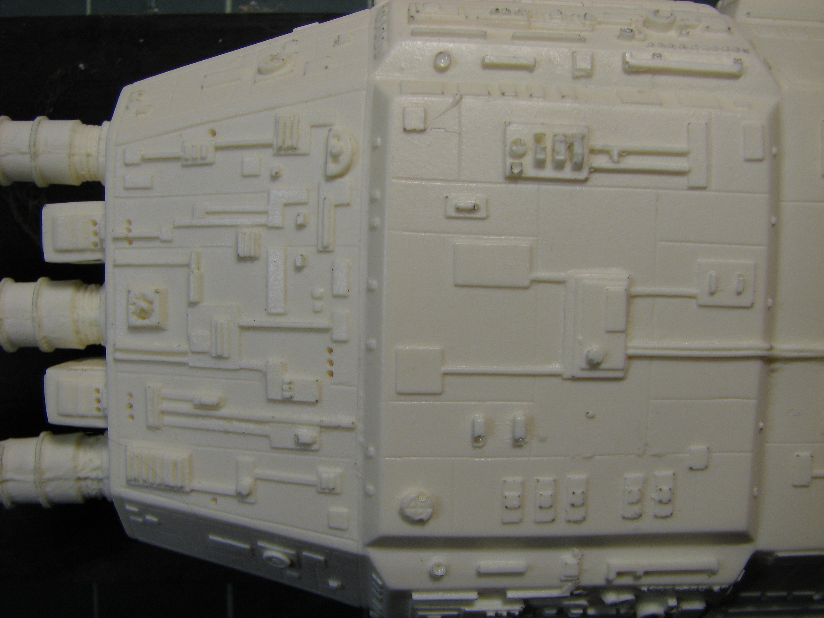
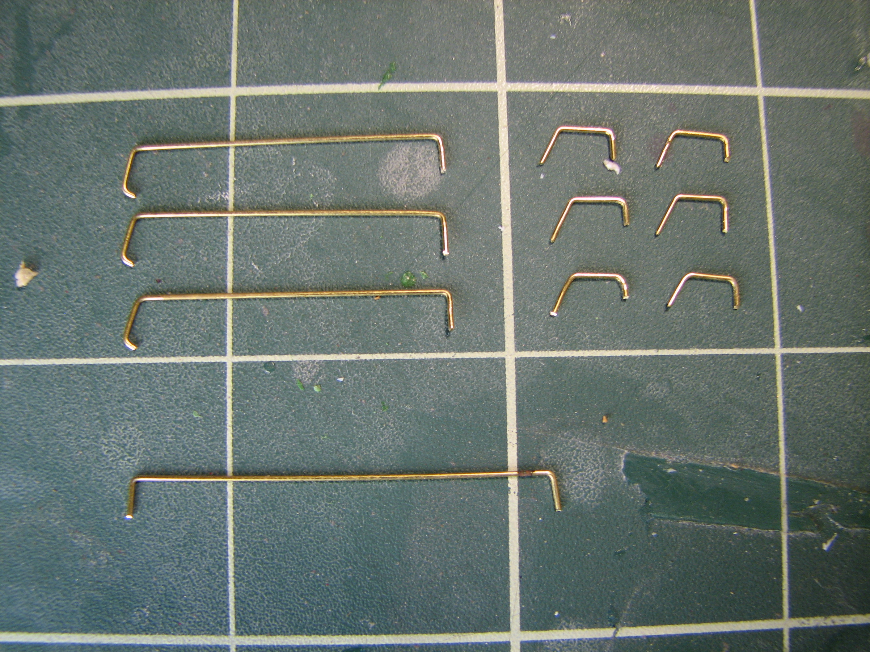
The kit provided thin brass wire for some engine plumbing on the aft underside of the ship. The instructions were fairly vague on the shapes to be made - bending templates would have been helpful. But I forged ahead making what looked close to the isometric drawings - assuming they're accurate.
I bent the brass with a "Grab Handler" wire bending jig to get the rough shapes, then finished then with pliers and cutters. Using a pin vise, I drilled #70 holes in the hull where the wire ends would go.
| Rough-shaped wire | Hull with piping holes drilled | Final shaped wires | Piping in place |
 |
 |
 |
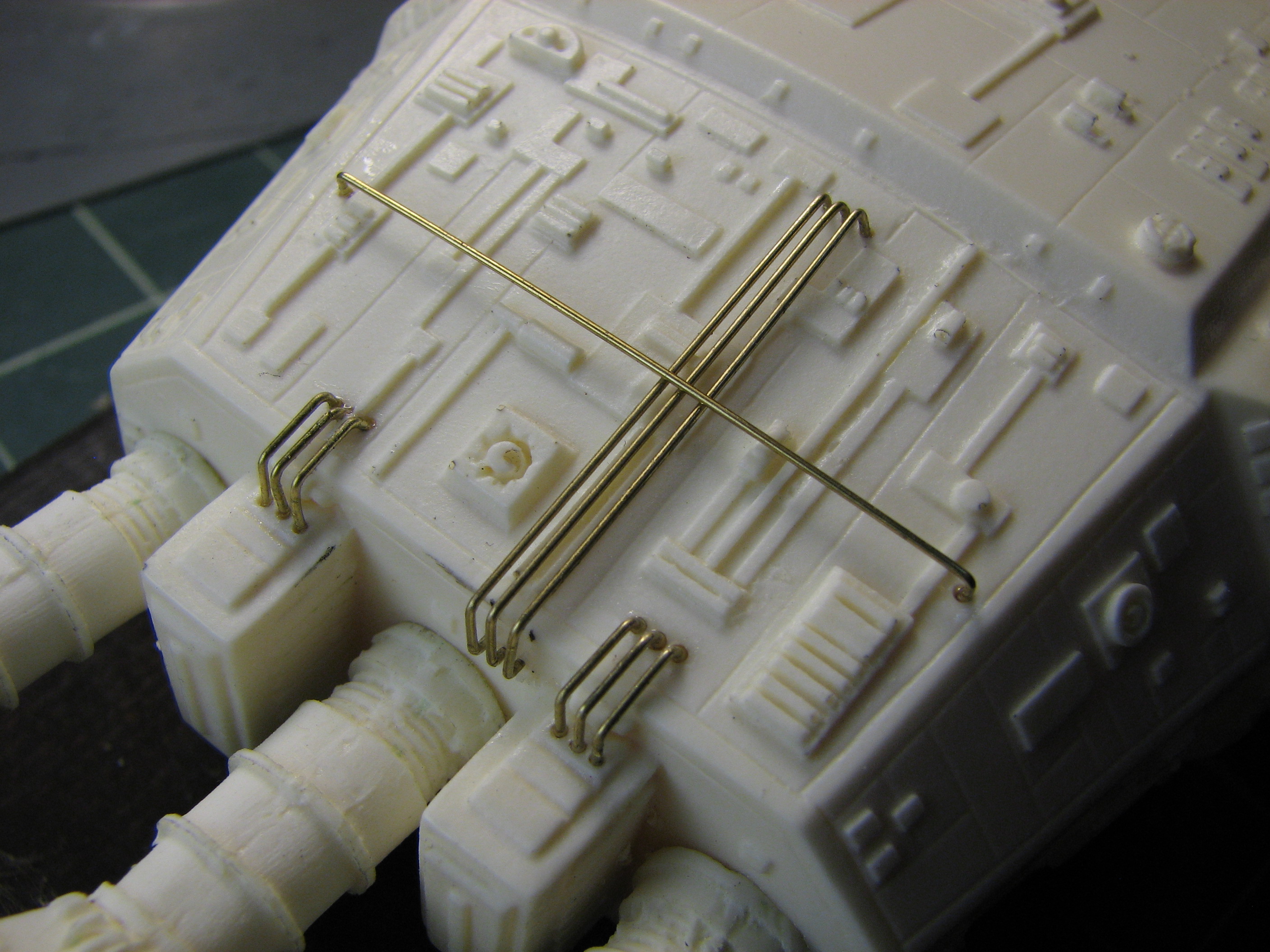 |
As it now looks - underside, underside aft close-up, topside

9/19/2010 - I started work on the flight deck interior. I cut two pieces out of clear plastic which I'll call floor and ceiling platforms on which the interior will be assembled - even though the floor and ceiling from a seated astronaut's perspective are not the same as these platforms. I made a page of scaled templates using the "done with mirrors" schematic from the Bizony book to help with the layout. Inside the ball I expoxied in place some girders on which the floor platform will rest. I started on the seats, using .04x.06" strip styrene, cemented together and cut to shape.


